


3Com Switch 8800 Configuration Guide Chapter 37 BGP/MPLS VPN Configuration
37-46
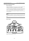
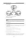
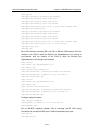
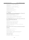
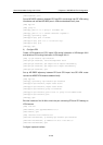
II. Network diagram
Internet
CE1
PE1
CE2 PE2
PE3
20.1.1.2
CE3
Hub Site
Spoke Site Spoke Site
VLAN201
172.18.0.1/16
VLAN201
172.16.0.1/16
VLAN202
172.17.0.1/16
VLAN201
172.15.0.1/16
Loopback0
22.1.1.1/32
Loopback0
33.1.1.1/32
Loopback0
11.1.1.1/32
Internet
CE1
PE1
CE2 PE2
PE3
20.1.1.2
CE3
Hub Site
Spoke Site Spoke Site
VLAN201
172.18.0.1/16
Spoke Site Spoke Site
VLAN201
172.18.0.1/16
VLAN201
172.16.0.1/16
VLAN202
172.17.0.1/16
VLAN201
172.15.0.1/16
Loopback0
22.1.1.1/32
Loopback0
33.1.1.1/32
Loopback0
11.1.1.1/32
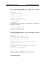
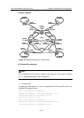
Figure 37-11 Network diagram for Hub&Spoke
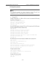
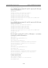
III. Configuration procedure
Note:
The following contents are omitted in this case: MPLS basic capacity configuration
between PEs, configuration between PE and P, configuration between CEs. For the
details refer to
37.4.1 .
1) Configure PE1
Configure two VPN-instances on PE1, set specified VPN-target for the routes received
from PE2 and PE3.
[PE1] ip vpn-instance vpn-instance2
[PE1-vpn-vpn-instance2] route-distinguisher 100:2
[PE1-vpn-vpn-instance2] vpn-target 100:11 import-extcommunity
[PE1-vpn-vpn-instance2] vpn-target 100:12 import-extcommunity
[PE1-vpn-instance2] quit
[PE1] ip vpn-instance vpn-instance3
[PE1-vpn-vpn-instance3] route-distinguisher 100:3
[PE1-vpn-vpn-instance3] vpn-target 100:2 export-extcommunity
[PE1-vpn-vpn-instance3] quit
Set up MP-EBGP adjacency between PE1 and CE1, import intra-CE1 VPN routes
learned into MBGP VPN-instance address family, with one routing loop permitted.