


3Com Switch 8800 Configuration Guide Chapter 25 Multicast VLAN Configuration
25-3
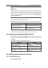
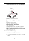
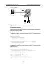
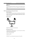
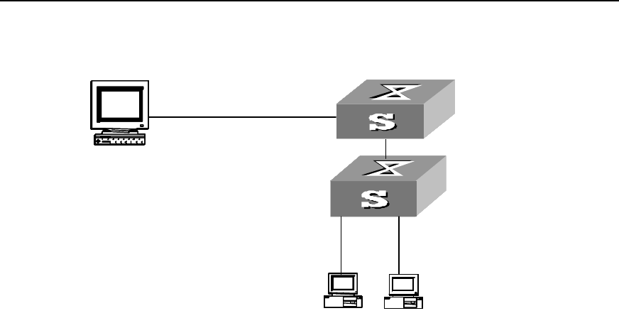
II. Network diagram
PC 2PC 2PC 2PC 2
PC 1PC 1PC 1PC 1
Sw itch A
PC 2PC 2PC 2
PC 1PC 1PC 1PC 1
Sw itch A
WorkstationWorkstation
Sw itch B
PC 2PC 2PC 2PC 2
PC 1PC 1PC 1PC 1
Sw itch A
PC 2PC 2PC 2
PC 1PC 1PC 1PC 1
Sw itch A
WorkstationWorkstation
Sw itch B
PC 2PC 2PC 2PC 2
PC 1PC 1PC 1PC 1
Sw itch A
PC 2PC 2PC 2PC 2
PC 1PC 1PC 1PC 1
Sw itch A
PC 2PC 2PC 2
PC 1PC 1PC 1PC 1
Sw itch A
PC 2PC 2PC 2
PC 1PC 1PC 1PC 1
Sw itch A
WorkstationWorkstationWorkstationWorkstation
Sw itch B
Figure 25-1 Network diagram for multicast VLAN configuration
III. Configuration procedure
Before performing the following configurations, you should configure the IP addresses
and connect the devices correctly.
1) Configure Switch A
Configure the IP address of the VLAN 2 interface to 168.10.1.1. Enable the PIM DM
protocol.
<Switch A> system-view
[Switch A] multicast routing-enable
[Switch A] vlan 2
[Switch A-vlan2] interface vlan-interface 2
[Switch A-Vlan-interface2] ip address 168.10.1.1 255.255.255.0
[Switch A-Vlan-interface2] pim dm
[Switch A-Vlan-interface2] quit
Configure the IP address of the VLAN 10 interface to 168.20.1.1. Enable the PIM DM
and IGMP protocols.
[Switch A] vlan 10
[Switch A-vlan10] interface vlan-interface 10
[Switch A-Vlan-interface10] ip address 168.20.1.1 255.255.255.0
[Switch A-Vlan-interface10] pim dm
[Switch A-Vlan-interface10]igmp enable
[Switch A-Vlan-interface10] quit
[Switch A]interface e1/1/10
[Switch A-Ethernet1/1/10]port link-type trunk
[Switch A-Ethernet1/1/10]port trunk permit vlan 10