


3Com Switch 8800 Configuration Guide Chapter 37 BGP/MPLS VPN Configuration
37-40
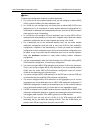
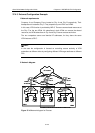
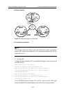
37.4.3 Extranet Configuration Example
I. Network requirements
Company A and Company B are located at City A and City B respectively. Their
headquarters is located at City C. They respectively own VPN1 and VPN2.
In this case, VPN function is provided by MPLS. There are some shared resources at
the City C for the two VPNs. All subscribers in both VPNs can access the shared
resources, but VPN subscribers in City A and City B cannot access each other.
The two companies cannot use identical IP addresses, for they share the same
VPN-instance at PE-C.
Note:
In the case the configuration is focused on controlling access authority of VPN
subscribers at different cities by configuring different VPN-target attributes at different
PEs.
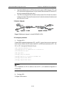
II. Network diagram
PC
CE-B
PCPC
CE-C
PCPC
CE-A
PCPC PC
CE-B
PCPC
CE-C
PCPC
CE-A
PCPC
VPN 1
VPN 2
PE-A
10.1.1.1
PE-B
30.1.1.1
PE-C
20.1.1.1
City A
City C City B
10.11.1.0/24 10.12.1.0/24
VLAN301
172.15.0.1/16
VLAN201
172.15.1.1/16
VLAN301
172.16.0.1/16
VLAN201
172.16.1.1/16
172.17.0.1/16
VLAN201
172.17.1.1/16
AS100
AS65011 AS65012 AS65013
VLAN301
SP network
VPN 1
VPN 2
PE-A
10.1.1.1
PE-B
30.1.1.1
PE-C
20.1.1.1
City A
City C City B
10.11.1.0/24 10.12.1.0/24
VLAN301
172.15.0.1/16
VLAN201
172.15.1.1/16
VLAN301
172.16.0.1/16
VLAN201
172.16.1.1/16
172.17.0.1/16
VLAN201
172.17.1.1/16
AS100
AS65011 AS65012 AS65013
VLAN301
SP network
PC
CE-B
PCPC
CE-C
PCPC
CE-A
PCPC
VPN 1
VPN 2
PE-A
10.1.1.1
PE-B
30.1.1.1
PE-C
20.1.1.1
City A
City C City B
10.11.1.0/24 10.12.1.0/24
VLAN301
172.15.0.1/16
VLAN201
172.15.1.1/16
VLAN301
172.16.0.1/16
VLAN201
172.16.1.1/16
172.17.0.1/16
VLAN201
172.17.1.1/16
AS100
AS65011 AS65012 AS65013
VLAN301
Figure 37-10 Network diagram for Extranet