


3Com Switch 8800 Configuration Guide Chapter 18 RIP Configuration
18-12
18.3 Displaying and Debugging RIP
After the above configuration, execute the display command in any view to display the
running of the RIP configuration, and to verify the effect of the configuration. Execute
the debugging command in user view to debug the RIP module. Execute the reset
command in RIP view to reset the system configuration parameters of RIP.
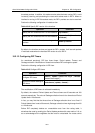
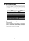
Table 18-17 Display and debug RIP
Operation Command
Display the current RIP running state and
configuration information.
display rip
Enable the RIP packet debugging information
debugging rip packet
Disable the RIP packet debugging information
undo debugging rip packet
Enable the debugging of RIP receiving packets
debugging rip receive
Disable the debugging of RIP receiving packets
undo debugging rip receive
Enable the debugging of RIP sending packet
debugging rip send
Disable the debugging of RIP sending packet
undo debugging rip send
Reset the system configuration parameters of RIP
reset
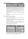
18.4 Typical RIP Configuration Example
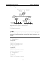
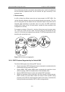
I. Network requirements
As shown in Figure 18-1, switch C connects to the subnet 117.102.0.0 through the
Ethernet port. The Ethernet ports of switches A and Switch B are respectively
connected to the network 155.10.1.0 and 196.38.165.0. Switch C, Switch A and Switch
B are connected via Ethernet 110.11.2.0. Correctly configure RIP to ensure that Switch
C, Switch A and Switch B can interconnect with each other.