


3Com Switch 8800 Configuration Guide Chapter 37 BGP/MPLS VPN Configuration
37-51
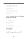
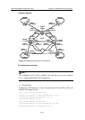
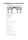
II. Network diagram
AS:100
CE1
PE1
CE2
PE2
PE3
Loopback0
1.1.1.1/32
Loopback0
2.2.2.2/32
Loopback0
3.3.3.3/32
VLAN211
172.11.11.2/24
VLAN211
172.11.11.1/24
VLAN212
172.21.21.2/24
VLAN212
172.21.21.1/24
AS:65002AS:65001
172.12.12.1/24
VLAN212
172.12.12.2/24
VLAN211
172.22.22.2/24
172.22.22.1/24
VLAN213
10.1.1.1/24 10.1.1.2/24
VLAN214
30.1.1.2/24
30.1.1.1/24
20.1.1.1/24
20.1.1.2/24
AS:65003
CE3
AS:65004
CE4
VLAN211
192.168.13.2/24
VLAN311
192.168.13.1/24 192.168.23.1/24
VLAN211
192.168.23.2/24
VLAN213
VLAN212
VLAN214
VLAN211
VLAN312
VLAN313
VLAN314
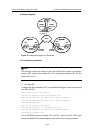
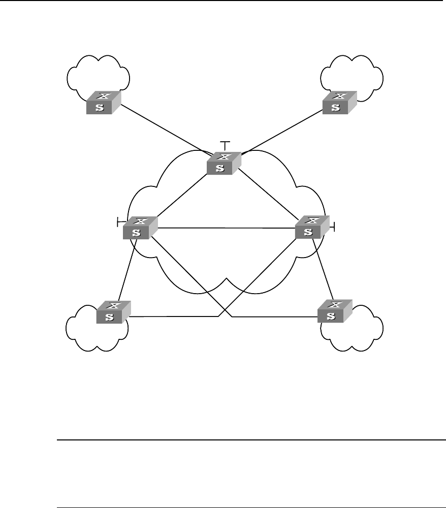
Figure 37-12 Network diagram for CE dual-home
III. Configuration procedure
Note:
The configuration of CE router is omitted in this case and you can refer to Section
37.4.1 Integrated BGP/MPLS VPN Configuration .
1) Configure PE1
Configure two VPN-instances 1.1 and 1.2 respectively for CE1 and CE2 on PE1, set
different VPN-targets for them.
[PE1] ip vpn-instance vpn-instance1.1
[PE1-vpn-vpn-instance1.1] route-distinguisher 1.1.1.1:1
[PE1-vpn-vpn-instance1.1] vpn-target 1.1.1.1:1
[PE1-vpn-vpn-instance1.1] quit
[PE1] ip vpn-instance vpn-instance1.2
[PE1-vpn-vpn-instance1.2] route-distinguisher 2.2.2.2:2
[PE1-vpn-vpn-instance1.2] vpn-target 2.2.2.2:2