


3Com Switch 8800 Configuration Guide Chapter 37 BGP/MPLS VPN Configuration
37-86
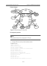
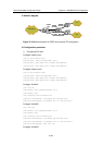
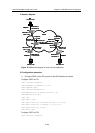
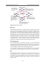
II. Network diagram
PC2
172.16.0.1/16
192.168.1.1/24
192.168.1.2/24
Ethernet2/1/0
20.1.1.2/24
Ethernet2/1/0
172.16.0.2/16
Ethernet1/1/0
20.1.1.1/24
CE2
PE1
PE2
PC3
172.19.0.1/16
Ethernet2/1/0
172.19.0.2/
Ethernet1/1/0
20.3.1.1/24
CE3
Ethernet2/1/0
20.3.1.2/24
Loopback0:
1.1.1.9/32
Loopback0:
2.2.2.9/32
PC1
172.18.0.1/16
Ethernet2/1/0
172.18.0.2/16
CE1
Ethernet3/1/0
20.2.1.2/24
Ethernet1/1/0
20.2.1.1/24
AS100
AS65420
AS65410
AS65430
Ethernet1/1/0
Ethernet1/1/0
PC2
172.16.0.1/16
192.168.1.1/24
192.168.1.2/24
Ethernet2/1/0
20.1.1.2/24
Ethernet2/1/0
172.16.0.2/16
Ethernet1/1/0
20.1.1.1/24
CE2
PE1
PE2
PC3
172.19.0.1/16
Ethernet2/1/0
172.19.0.2/16
Ethernet1/1/0
20.3.1.1/24
CE3
Ethernet2/1/0
20.3.1.2/24
Loopback0:
1.1.1.9/32
Loopback0:
2.2.2.9/32
PC1
172.18.0.1/16
Ethernet2/1/0
172.18.0.2/16
CE1
Ethernet3/1/0
20.2.1.2/24
Ethernet1/1/0
20.2.1.1/24
AS100
AS65420
AS65410
AS65430
Ethernet1/1/0
Ethernet1/1/0
PC2
172.16.0.1/16
192.168.1.1/24
192.168.1.2/24
Ethernet2/1/0
20.1.1.2/24
Ethernet2/1/0
172.16.0.2/16
Ethernet1/1/0
20.1.1.1/24
CE2
PE1
PE2
PC3
172.19.0.1/16
Ethernet2/1/0
172.19.0.2/
Ethernet1/1/0
20.3.1.1/24
CE3
Ethernet2/1/0
20.3.1.2/24
Loopback0:
1.1.1.9/32
Loopback0:
2.2.2.9/32
PC1
172.18.0.1/16
Ethernet2/1/0
172.18.0.2/16
CE1
Ethernet3/1/0
20.2.1.2/24
Ethernet1/1/0
20.2.1.1/24
AS100
AS65420
AS65410
AS65430
Ethernet1/1/0
Ethernet1/1/0
PC2
172.16.0.1/16
192.168.1.1/24
192.168.1.2/24
Ethernet2/1/0
20.1.1.2/24
Ethernet2/1/0
172.16.0.2/16
Ethernet1/1/0
20.1.1.1/24
CE2
PE1
PE2
PC3
172.19.0.1/16
Ethernet2/1/0
172.19.0.2/16
Ethernet1/1/0
20.3.1.1/24
CE3
Ethernet2/1/0
20.3.1.2/24
Loopback0:
1.1.1.9/32
Loopback0:
2.2.2.9/32
PC1
172.18.0.1/16
Ethernet2/1/0
172.18.0.2/16
CE1
Ethernet3/1/0
20.2.1.2/24
Ethernet1/1/0
20.2.1.1/24
AS100
AS65420
AS65410
AS65430
Ethernet1/1/0
Ethernet1/1/0
Figure 37-19 Network diagram for multi-role host application
III. Configuration procedure
1) Configure OSPF as the IGP protocol on the MPLS backbone network.
Configure OSPF on PE1:
[PE1] interface loopback 0
[PE1-LoopBack0] ip address 1.1.1.9 32
[PE1-LoopBack0] quit
[PE1] interface Ethernet1/1/0
[PE1-Ethernet1/1/0] ip address 192.168.1.1 24
[PE1-Ethernet1/1/0] quit
[PE1] ospf
[PE1-ospf-1] area 0
[PE1-ospf-1-area-0.0.0.0] network 192.168.1.0 0.0.0.255
[PE1-ospf-1-area-0.0.0.0] network 1.1.1.9 0.0.0.0
[PE1-ospf-1-area-0.0.0.0] quit
[PE1-ospf-1] quit
Configure OSPF on PE2:
[PE2] interface loopback 0