Installation
9
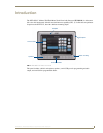
NXD-500i 5" Wall/Flush Mount Touch Panel with Intercom
Installation of an NXD-500i Touch Panel
The NXD-500i can be installed either directly into the (optional) CB-TP5i Rough-In Box or other solid
surface environment, using solid surface screws or the included locking tabs as mounting options. The
following sections describe mounting the touch panel directly into a pre-wall rough-in box, a solid
surface, drywall, or an NXA-RK5 Rack Mount Kit.
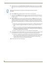
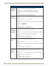
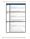
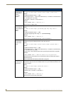
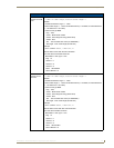
Pre-Wall Installation of the Rough-In Box
The CB-TP5i Rough-In Box (FG038-11) is an optional metallic box that is secured onto a stud/beam in
a pre-wall setting, where no walls are present. Installation procedures and configurations can vary,
depending on the installation environment. This section describes the installation procedures for the
most common installation scenarios.
1. Attach the optional Back Cover for the CB-TP5i (FG038-12) if necessary.
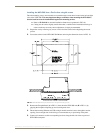
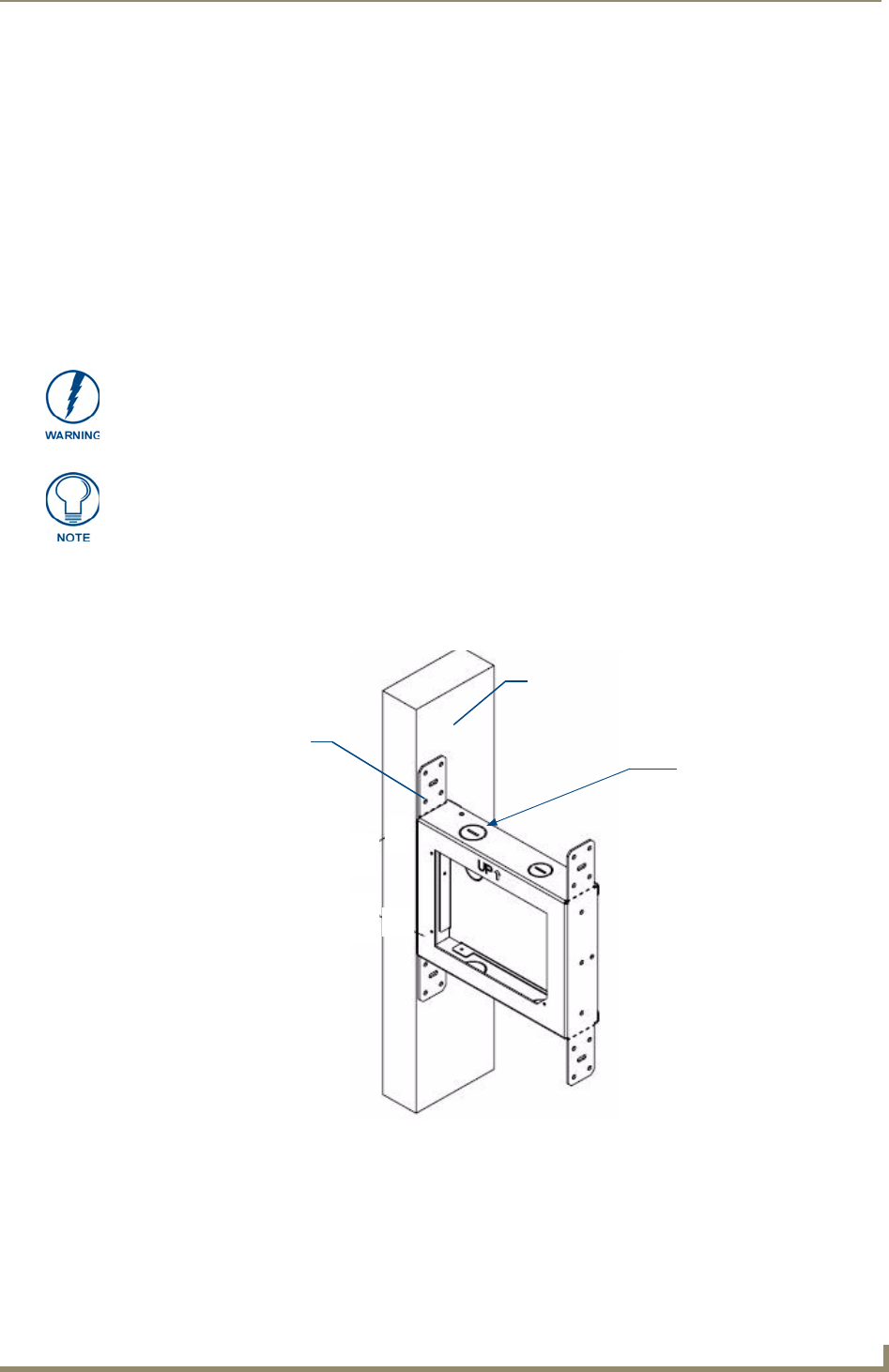
2. Fasten the CB-TP5i Rough-In Box to the stud through the holes on the Stud Mounting tabs (FIG. 5),
using either nails or screws.
3. Remove the appropriate wiring knockouts from the rough-in box (FIG. 5) to accommodate the
cables being threaded through to the NXD-500i touch panel.
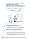
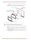
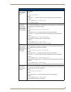
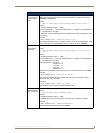
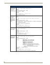
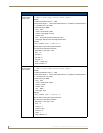
4. Thread the incoming Ethernet and USB wiring through the knockouts. Use of the left wiring
knockouts are recommended with this installation. Leave enough slack in the wiring to
accommodate any re-positioning of the panel.
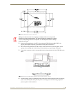
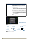
In order to guarantee a stable installation of the NXD-500i, the distance between the
CB-TP5i and the outer wall surface must be a minimum of .50 inches (1.27cm) and a
maximum of .875 inches (2.22cm).
Cutting out the surface slightly smaller than what is outlined in the installation
drawings, to allow any necessary cutout adjustments, is highly recommended.
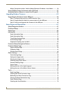
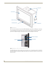
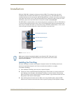
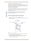
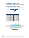
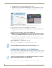
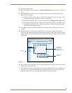
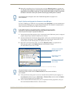
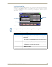
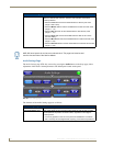
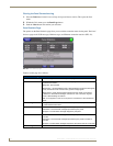
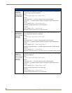
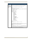
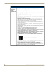
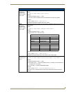
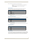
FIG. 5 CB-TP5i Rough-In Box components
Stud
Stud Mounting tabs
Wiring knockouts