


Installation
13
NXD-500i 5" Wall/Flush Mount Touch Panel with Intercom
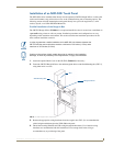
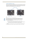
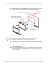
3. Remove the Faceplate/bezel (A in FIG. 9) from the main NXD-500i device (B in FIG. 9) by
gripping the faceplate and pulling up and then out with gentle outward force.
4. Thread the incoming Ethernet and USB wiring from their terminal locations through the surface
opening. Leave enough slack in the wiring to accommodate any re-positioning of the panel.
5. Connect both connectors to their corresponding locations along the left side of the NXD-500i touch
panel.
6. Test the incoming wiring by attaching the panel connections to their terminal locations and applying
power via the PoE Injector. Verify that the panel is receiving power and functioning properly to
prevent repetition of the installation.
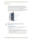
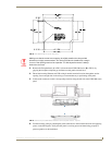
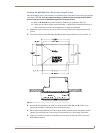
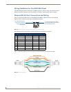
FIG. 8 NXD-500i Wall Mount panel dimensions
Making sure that the actual cutout opening be slightly smaller than the provided
dimensions is highly recommended. This action provides the installer with a margin
for error if the opening needs to be expanded. Too little drywall removed is always
better than too much.
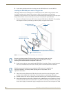
FIG. 9 Wall Mount panel (NXD-500i) installation view for drywall surfaces - top view
A
B