


Installation
18
NXD-500i 5" Wall/Flush Mount Touch Panel with Intercom
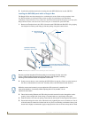
Wiring Guidelines for the NXD-500i Panel
The NXD-500i panel utilizes the Power over Ethernet protocol, where it draws power directly from its
Ethernet connection. Because of this, the panel has no need for standard power inputs or outputs.
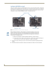
Ethernet/RJ-45 Port: Connections and Wiring
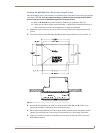
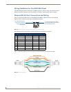
FIG. 12 describes the blink activity for the Ethernet 10/100 Base-T RJ-45 connector and cable. The
Ethernet cable is connected to the side of the Wall Mount panels.
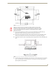
The following table lists the pinouts, signals, and pairing for the Ethernet connector.
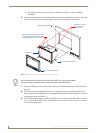
FIG. 13 diagrams the RJ-45 pinouts and signals for the Ethernet RJ-45 connector and cable.
FIG. 12 Ethernet connector (showing communication and connection LEDs)
Ethernet RJ-45 Pinouts and Signals
Pin Signals Connections Pairing Color
1 TX + 1 --------- 1 1 --------- 2 Orange-White
2 TX - 2 --------- 2 Orange
3 RX + 3 --------- 3 3 --------- 6 Green-White
4 PoE power 4 --------- 4 Blue
5 PoE power 5 --------- 5 4 --------- 5 Blue-White
6 RX - 6 --------- 6 Green
7 PoE power 7 --------- 7 7 --------- 8 Brown-White
8 PoE power 8 --------- 8 Brown
FIG. 13
RJ-45 wiring diagram
ETHERNET
10/100
A L
A - Activity LED (yellow)
lights when receiving or
transmitting Ethernet
data packets
L - Link LED (green) lights when
the Ethernet cables are connected
and terminated correctly.