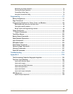
Configuring Communication
25
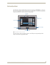
NXD-500i 5" Wall/Flush Mount Touch Panel with Intercom
Configuring and Using USB with a Virtual Master
NetLinx Studio can be set up to run a Virtual Master where the PC acts as the Master by supplying its
own IP Address for communication to the panel. The PC is first equipped with the USB driver, the panel
is then configured for USB communication, and then Studio is configured to act as the Master.
For a personal computer to establish a connection to a Modero panel via USB, the target computer must
have the appropriate AMX USB driver installed. This installation is bundled into the latest TPDesign4
software setup process or can be downloaded independently from the main Application Files page on
www.amx.com.
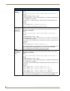
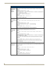
Step 1: Setup the Panel and PC for USB Communication
1.
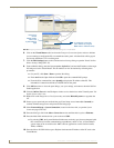
If you do not currently have the latest version of TPDesign4, navigate to www.amx.com > Tech
Center > Downloadable Files > Application Files > NetLinx Design Tools section of the website
and locate the File Transfer 2 executable (FT2Setup.exe). This will install the native RNDIS USB
driver when executed.
2. Download this executable file to a known location on your computer.
3. Launch the Setup.exe file and follow the on-screen prompts to complete the installation.
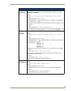
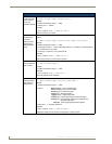
Step 2: Confirm the Installation of the USB Driver on the PC
The first time each AMX touch panel is connected to the PC, it is detected as a new hardware device and
the panel-specific USBLAN driver becomes associated with it. Each time thereafter, the panel is
"recognized" as a unique USBLAN device and the association to the driver is done in the background.
When the panel is detected for the first time, some user intervention is required during the association
between panel and driver.
1. After the installation of the USB driver has been completed, confirm the proper installation of the
large Type-A USB connector to the PC's USB port, and restart the PC.
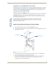
2. Connect the terminal end of the Ethernet cable to the connector on the side of the touch panel and
then apply power.
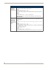
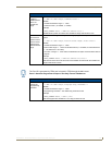
3. After the NXD-500i panel powers up, press and hold the Front Setup Access button for 4 seconds
to continue with the setup process and proceed to the Setup page.
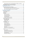
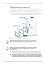
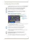
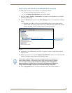
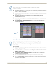
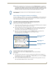
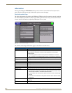
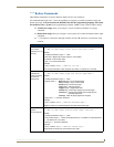
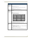
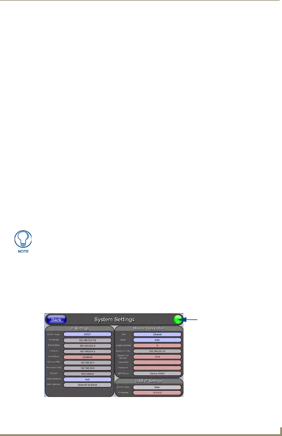
4. Select Protected Setup > System Settings (located on the lower-left) to open the System Settings
page (FIG. 19).
If the panel is already powered, continue with step 3.
The panel MUST be powered and configured for USB communication before
connecting the mini-USB connector to the panel’s Program Port.
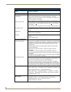
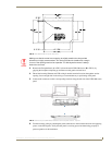
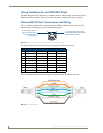
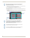
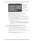
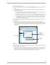
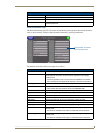
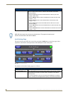
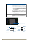
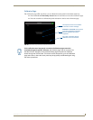
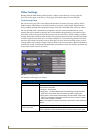
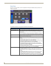
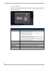
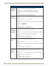
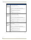
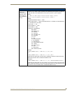
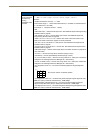
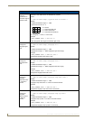
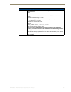
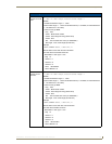
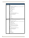
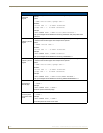
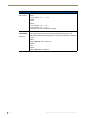
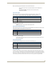
FIG. 19 System Settings page - using a USB Connection type
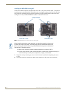
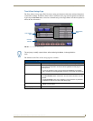
No connection is established until
the Virtual Master becomes
active within NetLinx Studio
Red Connection Status icon -
Green Connection Status icon -
indicates no connection to a Virtual
indicates communication to a Virtual
Master
Master