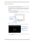
Configuring Communication
29
NXD-500i 5" Wall/Flush Mount Touch Panel with Intercom
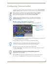
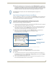
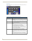
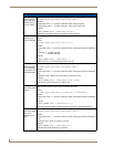
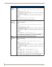
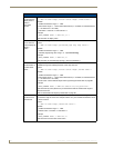
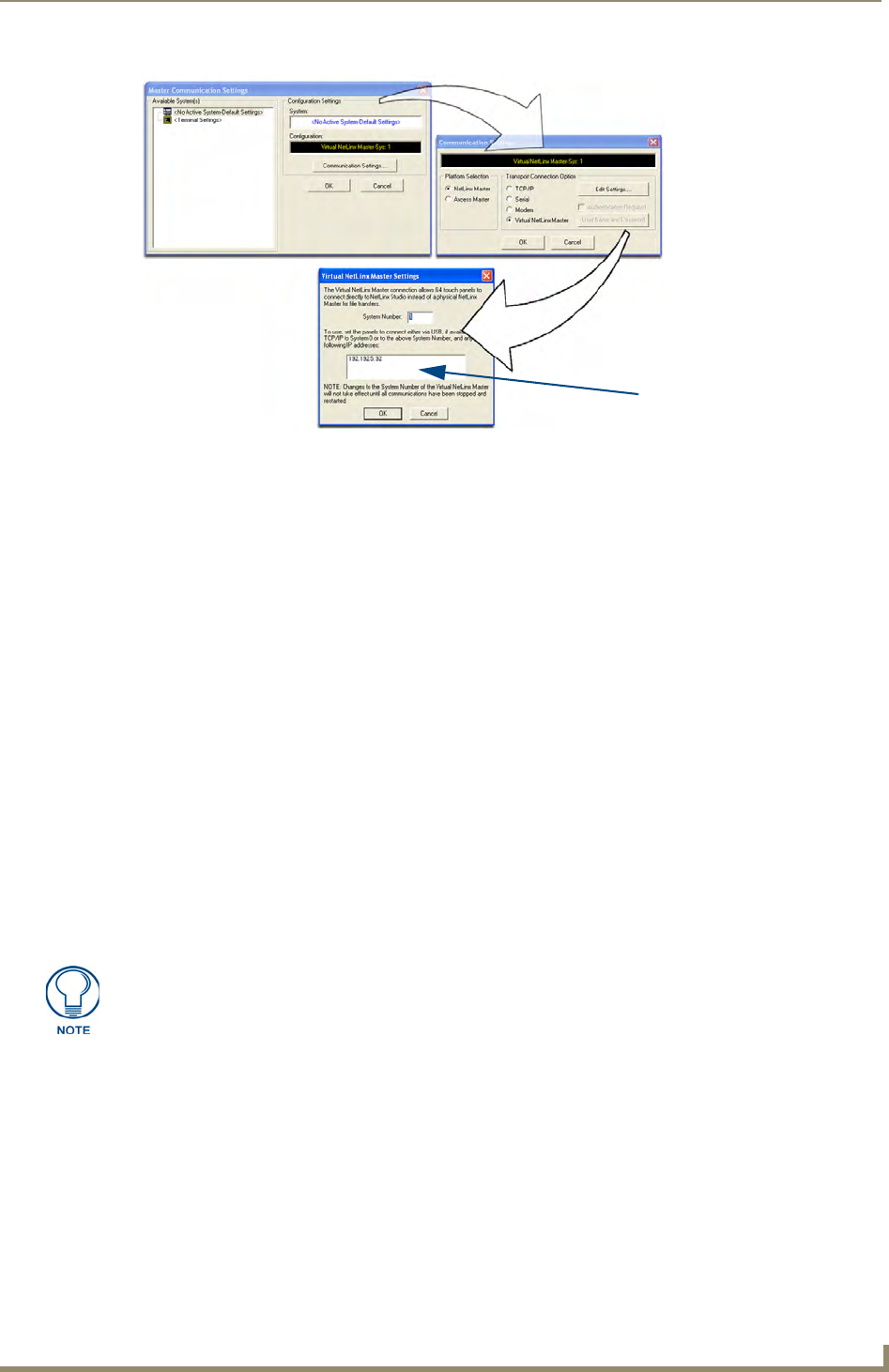
6. Click on the Virtual Master radio box from the Transport Connection Option section to configure
the PC to communicate directly with a panel. Everything else, such as the Authentication, is greyed
out because this action is not going through the Master’s UI.
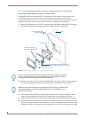
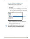
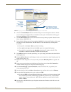
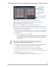
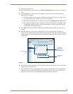
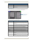
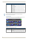
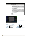
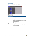
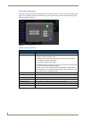
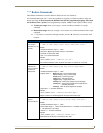
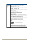
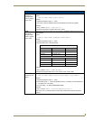
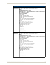
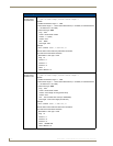
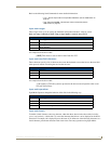
7. Click the Edit Settings button on the Communications Settings dialog to open the Virtual NetLinx
Master Settings dialog (FIG. 22).
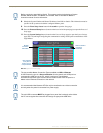
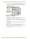
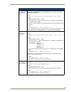
8. From within this dialog, enter the System number (default is 1).
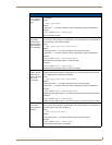
9. Click OK three times to close the open dialogs, save the settings, and return to the main NetLinx
Studio application.
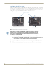
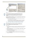
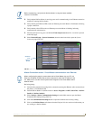
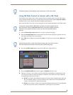
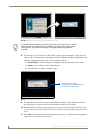
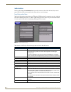
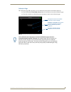
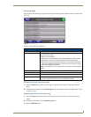
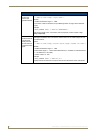
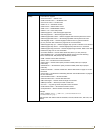
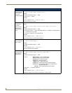
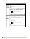
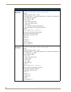
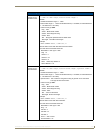
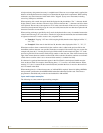
10. Click the OnLine Tree tab in the Workspace window to view the devices on the Virtual System. The
default System value is one.
11. Right-click on the Empty Device Tree/System entry and select Refresh System to re-populate the
list.
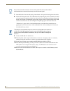
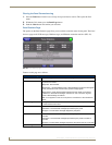
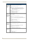
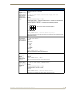
The panel will not appear as a device below the virtual system number (in the Online Tree tab)
until both the system number used in step 7 for the VNM is entered into the Master Connection
section of the System Connection page and the panel is restarted.
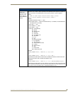
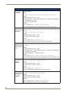
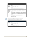
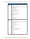
The Connection status turns green after a few seconds to indicate an active USB connection to
the Virtual Master on the PC. No Lock icon is displayed because this USB connection is not
secured and does not require a username and password.
If a few minutes have gone by and the System Connection icon still does not turn green, repeat
the USB connection and Virtual Master setup procedures (outlined in this section). Refreshing
the System sends out a request to the panel to respond and completes the communication
(turning the System Connection icon green).
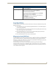
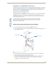
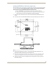
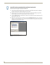
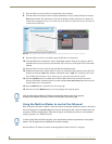
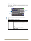
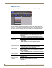
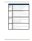
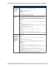
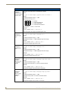
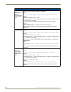
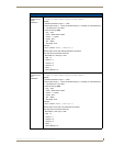
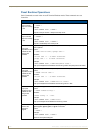
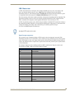
Step 5: Confirm and View the current AMX USB device connections
Use the CC-USB Type-A to Mini-B 5-wire programming cable (FG10-5965) to provide communication
between the mini-USB Program port on the touch panel and the PC. This method of communication is
used to transfer firmware KIT files and TPD4 touch panel files.
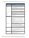
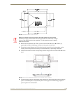
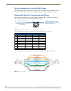
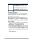
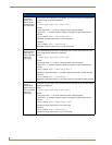
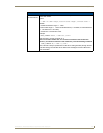
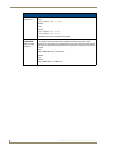
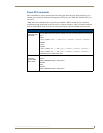
FIG. 22 Assigning Communication Settings for a Virtual Master
(not needed as this is a direct
USB connection)
IP Address of computer
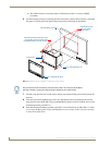
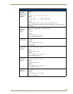
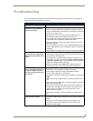
If the G4 panel does not appear, refer to the Troubleshooting section on page 131 for
more information.