


Upgrading Modero Firmware
45
NXD-500i 5" Wall/Flush Mount Touch Panel with Intercom
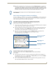
10. Right-click on the Empty Device Tree/System entry and select Refresh System to re-populate the
list. The panel will not appear as a device below the virtual system number in the Online Tree tab
until both the system number used in step 7 for the Virtual NetLinx Master (VNM) is entered into
the Master Connection section of the System Connection page and the panel is restarted.
Step 3: Confirm and Upgrade the firmware via the USB port
Use the CC-USB Type-A to Mini-B 5-wire programming cable (FG10-5965) to provide communication
between the mini-USB Program port on the touch panel and the PC. This method of communication is
used to transfer firmware Kit files and TPD4 touch panel files.
1. Verify that the direct USB connection (Type-A on the panel to mini-USB on the panel) is configured
properly using the steps outlined in the previous two sections.
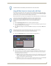
2. After the Communication Verification dialog window verifies active communication between the
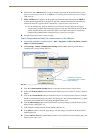
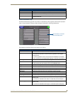
Virtual Master and the panel, click the OnLine Tree tab in the Workspace window (FIG. 33) to
view the devices on the Virtual System. The default System value is one.
3. Right-click on the System entry (FIG. 33) and select Refresh System to re-populate the list.
Verify the panel appears in the OnLine Tree tab of the Workspace window.
The default Modero panel value is 10001.
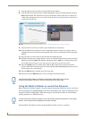
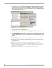
4. If the panel firmware being used is not current, download the latest Kit file by first logging in to
www.amx.com and then navigate to Tech Center > Firmware Files and from within the Modero
section of the web page locate your Modero panel.
5. Click on the desired Kit file link and after you’ve accepted the Licensing Agreement, verify you
have downloaded the Modero Kit file to a known location.
If the G4 panel does not appear, refer to the Troubleshooting section on page 131 for
more information.
A mini-USB connection is only detected after it is installed onto an active panel.
Connection to a previously powered panel which then reboots, allows the PC to
detect the panel and assign an appropriate USB driver.
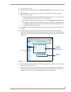
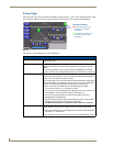
FIG. 33 NetLinx Workspace window (showing the panel connection via a Virtual NetLinx Master)
Showing the Virtual Master
firmware version and
device number
Showing the current Modero
panel firmware version and
device number
Shows NetLinx Studio
version number
The panel firmware is shown on the right of the listed panel.
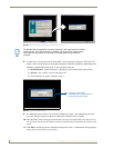
Download the latest firmware file from www.amx.com and then save the Kit file to
your computer.