Installation
16
NXD-500i 5" Wall/Flush Mount Touch Panel with Intercom
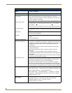
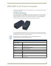
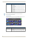
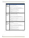
The USB connectors can be from either a USB extension cable or a wireless USB RF
transmitter.
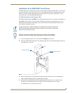
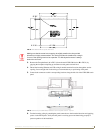
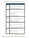
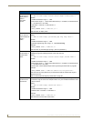
6. Test the incoming wiring by connecting the panel connections to their terminal locations. Verify that
the panel is receiving power and functioning properly before finalizing the installation.
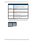
7. Carefully slide the main unit into the cutout, making sure that the locking tabs lie flush against the
back box.
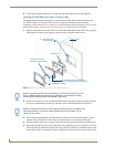
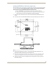
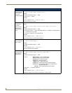
8. Insert and secure three #4 Mounting Screws (not included) into the corresponding holes located
along the sides of the NXD-500i, using a grounded Phillips-head screwdriver, until the unit is secure
and flush against the wall (FIG. 11).
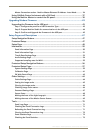
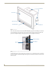
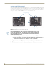
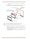
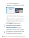
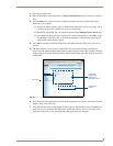
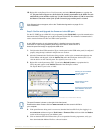
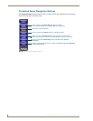
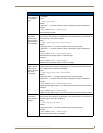
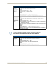
9. Place the Faceplate/Trim Ring assembly (A in FIG. 11) back onto the device (B in FIG. 11). Make
sure to align the Microphone, Light, and PIR Motion sensor locations to their respective openings
on the front bezel/faceplate.
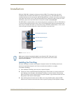
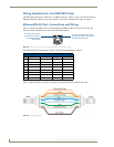
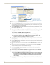
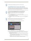
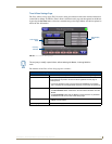
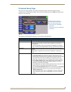
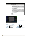
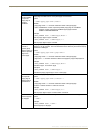
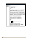
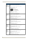
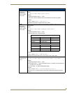
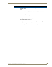
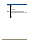
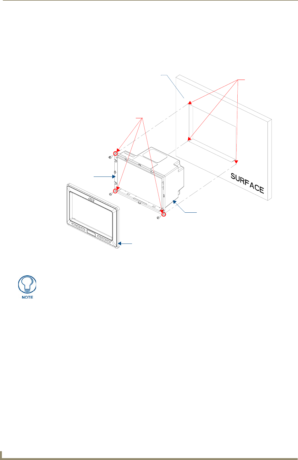
FIG. 11 Wall Mount panel installation configuration for flat surfaces
B - Main NXD-500i unit
Install the three #4 Mounting Screws
Flat installation surface
A - Faceplate/Trim Ring
Locking Tab
Attachment is done
along the edges
of the cutout
(not included) into these three holes
(suggested length of screws is 0.25")
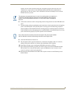
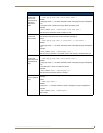
Do not disconnect the connectors from the touch panel. The unit must be installed
with the necessary connectors before being inserted into the solid surface.