


Table of Contents
i
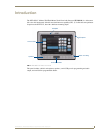
NXD-500i 5" Wall/Flush Mount Touch Panel with Intercom
Table of Contents
Introduction ........................................................................................................1
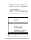
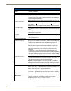
NXD-500i Specifications ........................................................................................... 3
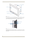
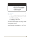
Front Bezel Button.................................................................................................... 5
Ethernet and mini-USB Ports .................................................................................... 5
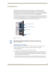
Installation ..........................................................................................................7
Installing the Trim Ring ............................................................................................. 7
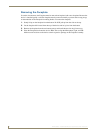
Removing the Faceplate ........................................................................................... 8
Installation of an NXD-500i Touch Panel................................................................... 9
Pre-Wall Installation of the Rough-In Box........................................................................ 9
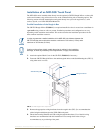
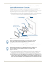
Installing the NXD-500i panel within a Rough-In Box.................................................... 10
Installing the NXD-500i into drywall ............................................................................. 12
Installing the NXD-500i into a Flat Surface using #4 screws ......................................... 15
Installing an NXD-500i into a Rack Mount Kit (NXA-RK5) ............................................. 17
Wiring Guidelines for the NXD-500i Panel.............................................................. 18
Ethernet/RJ-45 Port: Connections and Wiring ........................................................ 18
NXD-500i Touch Panel Accessories ..................................................................19
PS-POE-AF PoE Injector.......................................................................................... 19
Panel Calibration ..............................................................................................21
Calibrating the Modero Panel................................................................................. 21
Configuring Communication .............................................................................23
Modero Setup and System Connection .................................................................. 23
Configuring and Using USB with a Virtual Master .................................................. 25
Step 1: Setup the Panel and PC for USB Communication ............................................. 25
Step 2: Confirm the Installation of the USB Driver on the PC ....................................... 25
Step 3: Confirm and View the current AMX USB device connections ........................... 27
Step 4: Use the USB to Configure a Virtual Master (using NetLinx Studio)................... 28
Step 5: Confirm and View the current AMX USB device connections ........................... 29
Configuring a Wired Ethernet Connection.............................................................. 31
Step 1: Configure the Panel’s Wired IP Settings..................................................... 31
IP Settings section - Configuring a DHCP Address over Ethernet................................. 31
IP Settings section - Configuring a Static IP Address over Ethernet ............................. 31
Step 2: Choose a Master Connection Mode Setting............................................... 32
Step 3: Configure an Ethernet Connection Type .................................................... 32
Master Connection section - Virtual Master communication over Ethernet .................. 33
Master Connection section - NetLinx Master Ethernet IP Address - URL Mode............ 35
Master Connection section - NetLinx Master Ethernet IP Address - Listen Mode......... 36