Installation
14
NXD-500i 5" Wall/Flush Mount Touch Panel with Intercom
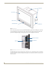
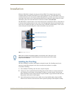
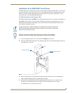
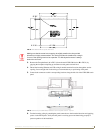
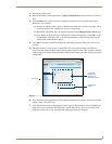
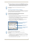
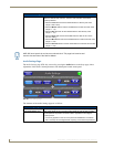
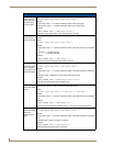
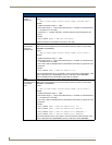
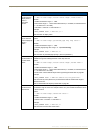
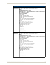
7. Push the back box into the wall opening. Insure that the locking tabs lie flush against the back box.
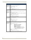
8. Extend the locking tabs on the sides of the back box by tightening the screws inside the box. Not all
of the tabs must be extended to lock the back box in place, but extending a minimum of the top and
bottom tabs is highly recommended. Apply enough pressure to the screw head to keep the box flush
with the wall: this ensures that the locking tabs will tighten up against the inside of the wall.
The back box is clear to allow visual confirmation that the tabs have been extended and are
gripping the wall. This also allows visual confirmation if the entire assembly has to be removed
from the wall for any reason.
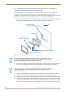
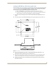
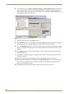
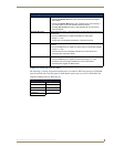
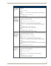
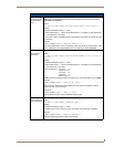
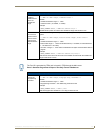
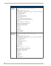
9. Install the NXD-500i into the back box.
10. The microphone cable is taped to the back box. Connect the microphone cable to its connector,
making sure that the cable does not interfere with reattachment of the Faceplate.
11. Install the two Plastite screws attaching the NXD-500i to the back box (FIG. 6).
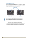
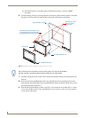
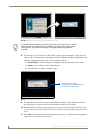
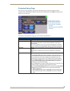
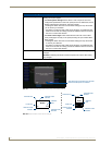
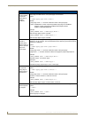
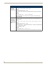
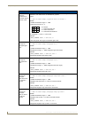
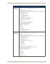
12. Place the Faceplate/Trim Ring assembly (A in FIG. 9) back onto the main NXD-500i unit (B in
FIG. 9). Make sure to align the Microphone, Light, and PIR Motion sensor locations to their
respective openings on the front faceplate/bezel.
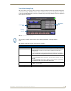
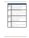
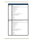
13. Reconnect the terminal Ethernet and USB to their respective locations on the Ethernet port and
NetLinx Master.
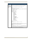
Do not disconnect the connectors from the touch panel. The unit must be installed
with the attached connectors before being inserted into the drywall.
The maximum recommended torque to screw in the locking tabs on the back box is
105 IN-OZ [74 N-CM]. Applying excessive torque while tightening the locking tab
screws, such as with powered screwdrivers, can strip out the tabs or damage the
back box.