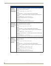
Upgrading Modero Firmware
44
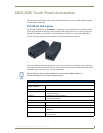
NXD-500i 5" Wall/Flush Mount Touch Panel with Intercom
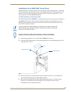
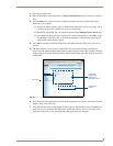
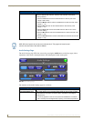
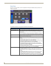
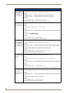
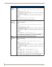
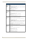
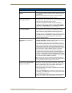
6. Press the on-screen Reboot button to save any changes and restart the panel. Remember that the
panel’s connection type must be set to USB prior to rebooting the panel and prior to inserting the
USB connector.
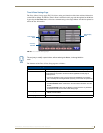
7. ONLY AFTER the unit displays the first panel page should the mini-USB connector THEN be
inserted into the Program Port on the panel. It may take a minute for the panel to detect the new
connection and send a signal to the PC, indicated by a green System Connection icon.
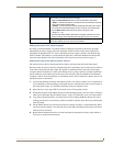
If a few minutes have gone by and the System Connection icon still does not turn green,
complete the procedures in the following section to set up the Virtual Master and refresh the
System from the Online Tree. This action sends out a request to the panel to respond and
completes the communication, turning the System Connection icon green.
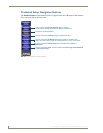
8. Navigate back to the System Connection page.
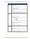
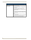
Step 2: Prepare NetLinx Studio for communication via the USB port
1.
Launch NetLinx Studio 2.x (default location is Start > Programs > AMX Control Disc > NetLinx
Studio 2 > NetLinx Studio 2).
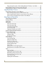
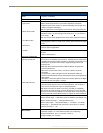
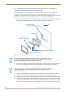
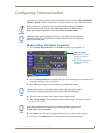
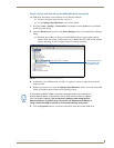
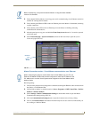
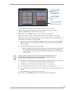
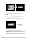
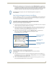
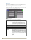
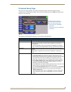
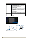
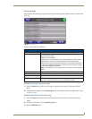
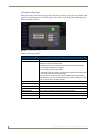
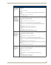
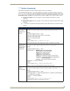
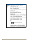
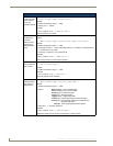
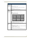
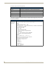
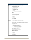
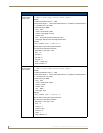
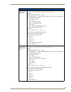
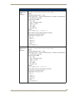
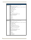
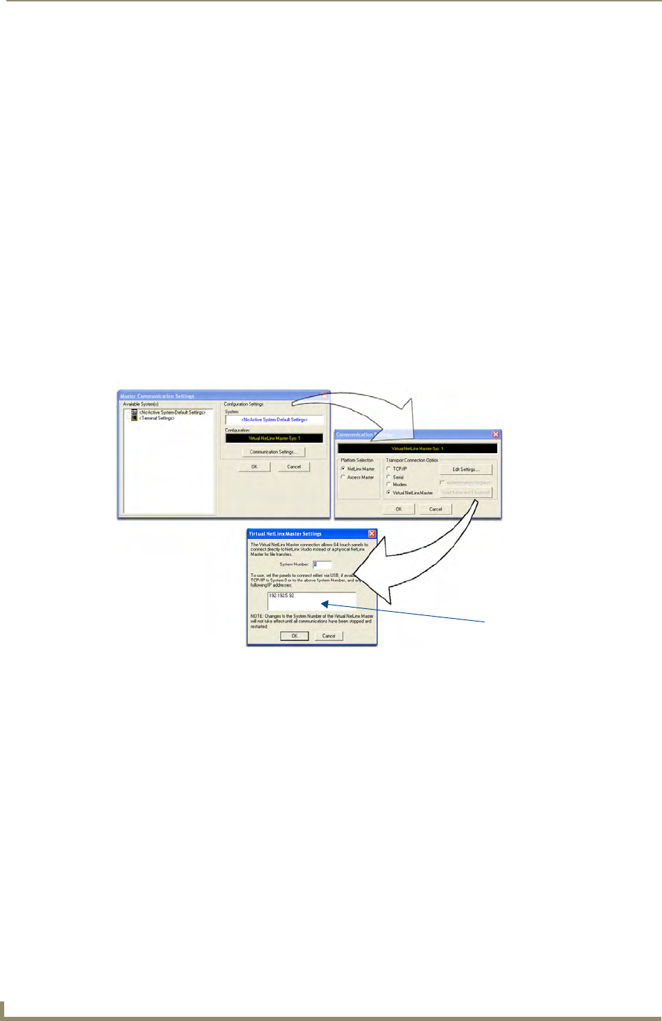
2. Select Settings > Master Communication Settings from the Main menu to open the Master
Communication Settings dialog (FIG. 32).
3. Click the Communications Settings button to open the Communications Settings dialog.
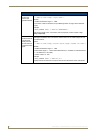
4. Click on the NetLinx Master radio button from the Platform Selection section to work as a NetLinx
Master.
5. Click on the Virtual Master radio box from the Transport Connection Option section to configure
the PC to communicate directly with a panel. Everything else, such as the Authentication, is greyed-
out because the communication is not going through the Master’s UI.
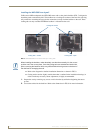
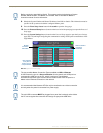
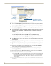
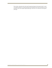
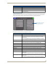
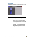
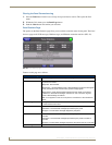
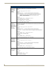
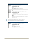
6. Click the Edit Settings button on the Communications Settings dialog to open the Virtual NetLinx
Master Settings dialog (FIG. 32).
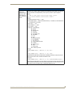
7. From within this dialog, enter the System number (default is 1).
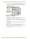
8. Click OK three times to close the open dialogs, save the settings, and return to the main NetLinx
Studio application.
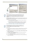
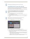
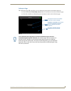
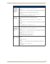
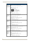
9. Click the OnLine Tree tab in the Workspace window to view the devices on the Virtual System. The
default System value is one.
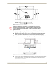
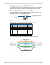
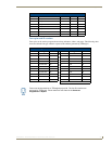
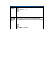
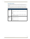
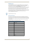
FIG. 32 Assigning Communication Settings for a Virtual Master
(not needed as this is a direct
USB connection)
IP Address of computer