Installation
10
NXD-500i 5" Wall/Flush Mount Touch Panel with Intercom
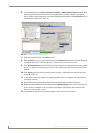
5. Install the drywall/sheetrock before inserting the main NXD-500i device into the CB-TP5i.
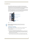
Installing the NXD-500i panel within a Rough-In Box
The Rough-In Box must be mounted prior to continuing this section. Refer to the procedures in the
Pre-Wall Installation of the Rough-In Box section on page 9 for detailed pre-wall installation
instructions. Verify that all necessary cables have been threaded through the knockouts on the left of the
Rough-In Box and the connections have been tested prior to installation of the NXD-500i.
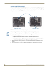
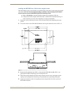
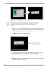
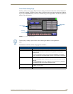
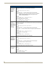
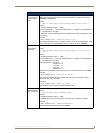
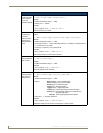
1. Remove the Faceplate bezel (A in FIG. 6) from the main NXD-500i unit (B in FIG. 6) by gripping
the faceplate from the top and lifting up and then pulling with gentle outward force.
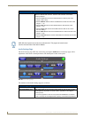
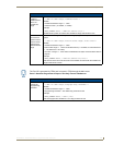
2. Gently unscrew the two screws attaching the NXD-500i to its back box. These are at the bottom of
the device, underneath the touch screen. Carefully remove the NXD-500i from the back box.
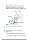
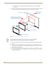
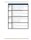
3. Thread the incoming Ethernet and USB wiring from their terminal locations through the surface
opening. Leave enough slack in the wiring to accommodate any re-positioning of the panel.
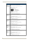
4. Push the back box into the wall opening. Insure that the locking tabs lie flush against the back box.
5. Extend the locking tabs on the sides of the back box by tightening the screws inside the box. Not all
of the tabs must be extended to lock the back box in place, but extending a minimum of the top and
bottom tabs is highly recommended. Apply enough pressure to the screw head to keep the box flush
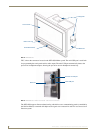
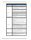
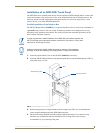
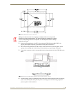
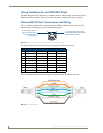
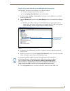
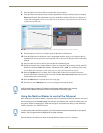
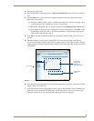
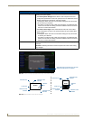
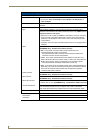
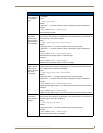
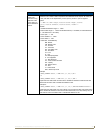
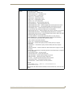
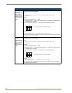
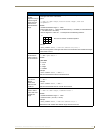
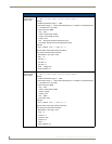
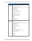
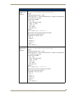
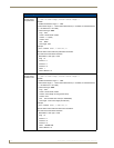
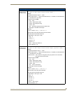
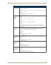
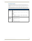
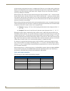
FIG. 6 NXD-500i panel installation into a CB-TP5i (pre-wall construction)
B - Main NXD-500i unit consists of
C - Optional CB-TP5i
Stud
the touch panel and back box housing
rough-in/wallbox
A - Faceplate/Trim Ring
Screws for mounting
Back Box to touch panel
Locking Tab
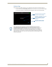
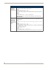
Be sure to pull the faceplate UP before pulling it out and away from the rest of the
device. Pulling straight outward may lead to damage to the faceplate, including
breaking off the tabs that attach the faceplate to the device.
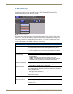
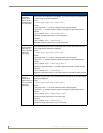
While the screws are loosened, you can adjust the LCD to ensure it is parallel to the
sides of the backbox, if necessary. While adjusting the LCD is possible, it is not
required in most cases.