


Installation
15
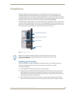
NXD-500i 5" Wall/Flush Mount Touch Panel with Intercom
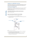
Installing the NXD-500i into a Flat Surface using #4 screws
Three #4 mounting screws (not included) are secured through circular holes located at the left and right
sides of the NXD-500i. The most important thing to remember when mounting the NXD-500i is
that the back box must be installed flush against the mounting surface.
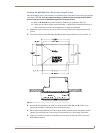
Refer to SP-2261-02 for detailed installation dimensions (reproduced in FIG. 10).
Cutting out the surface slightly smaller than what is outlined in the installation drawings in
order to make any necessary cutout adjustments, is highly recommended.
1. Prepare the area by removing any screws or nails from the surface before beginning the cutout
process.
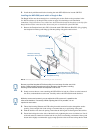
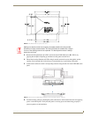
2. Cut out the surface for the NXD-500i Wall Mount unit using the dimensions shown in FIG. 10.
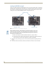
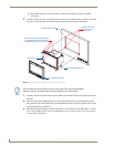
3. Remove the Faceplate/bezel (A in FIG. 11) from the main NXD-500i unit (B in FIG. 11) by
gripping the faceplate and pulling up and out with gentle force.
4. Thread the incoming Ethernet and USB wiring from their terminal sources through the surface
opening. Leave enough slack in the wiring to accommodate any re-positioning of the panel.
5. Connect all connectors to their corresponding locations along the left side of the un-powered
NXD-500i touch panel.
FIG. 10 NXD-500i Wall Mount panel dimensions using #4 mounting screws