


Overview
3
TVM-1600 Endeleo Managed TV Distribution Hub
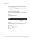
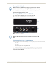
Rear Panel
The rear panel has connectors to enable the connection of an RF feed, and enable this to be cascaded to
subsequent hubs. There are also connectors for connection of a serial control device, an IR output
connection for remote control of various devices (up to 4 devices supported), and a 10 baseT network
connector.
RF In
Multiple TVM-1600s can be cascaded together by looping the RF feeds together.
Simply take an RF Out connection and connect it to the RF In port (FIG. 3) of the subsequent TVM-
1600. The insertion loss on the RF Out connector is 3.6dB.
You can connect multiple TVM-1600s through the RF Out connector as long as the inserted feed is
higher than +20dB.
Inserting a splitter before the installed TVM-1600s ensures that all TVM-1600s receive the same RF
levels.
The RF input supports input levels in the range 80-105dBµV.
It is important that there is a maximum of 6dB variation between channels.
RF Out
Use the RF Out connection (FIG. 3) to cascade TVM-1600s together. TV Channels can now be
distributed to another TVM-1600 if this connection is used with another TVM-1600 (connected to its RF
In port).
Serial Port
The serial port (FIG. 3) enables an administrator to control the various functions so the TVM-1600
hardware from a command line prompt. The connector is a 9-pin female D connector designed to be used
with a PC and straight-through cable.
Connecting a laptop or other computer device can be achieved using straight through (male-female)
serial cable.
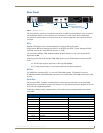
FIG. 3 TVM-1600 Rear panel
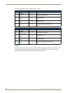
Serial Port
DB-9F Function Abbreviation
Pin 1 Not used NC
Pin 2 Transmit Data TD or TX or TXD
Pin 3 Receive Data RD or RX or RXD
Pin 4 Data Set Ready DSR
Pin 5 Signal Ground GND
Pin 6 Data Terminal Ready DTR
Pin 7 Not Used NC
Pin 8 Not Used NC
Pin 9 Not Used NC
RF In
RF Out
Serial Port
IR Output Control Port
Network Port
IEC Power Connector