


Wiring and Connections
13
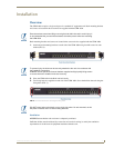
UDM-1604 Endeleo Multi-Format Distribution Hub
UDM Hubs allow you to compensate brightness, sharpness and skew delay via options in the Status page
of the UDM’s built-in WebConsole (see the Video Compensation section on page 21).
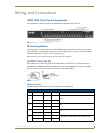
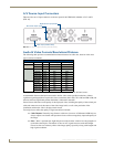
VIDEO IN Connectors (HD15)
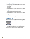
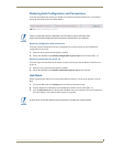
FIG. 11 provides the pin layout for the VIDEO IN HD15 Connectors:
The table below describes the pinout configuration on the VIDEO IN HD15 connector for VGA,
Component, S-Video and Composite connections:
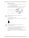
Connecting a VGA Video Input
1.
Connect one end of a VGA cable to the source device’s VGA output port.
2. Attach the other end of the cable to the appropriate VIDEO IN connection (A or B) on the UDM.
For example, connect to the Video In connection on Input A of the Hub.
3. Connect any audio to the analog (RCA) audio connectors or digital (SPDIF) connector.
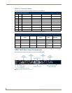
FIG. 11 VIDEO IN HD15 Connector
VIDEO IN HD15 Pinout Configuration
Input Pin VGA Component S-Video Composite
1 Red Y Luminance CVBS1
6 Red - Ground Y - Ground Luminance - Ground CVBS1 Ground
2 Green Pb - CVBS2
7 Green - Ground Pb - Ground - CVBS2 Ground
3 Blue Pr Chrominance CVBS3
8 Blue - Ground Pr - Ground Chrominance - Ground CVBS3 Ground
13 Horizontal Sync - - -
14 Vertical Sync - - -
12345
67891
1112131415
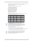
The UDM-HD15RCA3F Endeleo HD15 to 3x RCA Breakout Cable
(FG-HD15RCA3F) referenced in the table above is different from a standard RCA
cable, and an RCA cable cannot be used in its place (the Y, Pb, and Pr connections
are shifted from the VESA standard). If a standard cable is to be used, you will have
to swap the connectors. Contact AMX Technical Support for details.
Ensure Input A is configured as a “VGA Input” and named appropriately within the
“Inputs” section of the UDM’s built-in WebConsole. Also ensure the correct Audio
Type (Analog L/R or S/PDIF) is selected for the relevant input. Refer to the
Configuration section on page 21 for details.