Directives Reference
7-50 Copyright © 2000, 2001 ARM Limited. All rights reserved. ARM DUI 0068B
7.7.1 ALIGN
The
ALIGN
directive aligns the current location to a specified boundary by padding with
zeroes.
Syntax
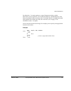
ALIGN {expr{,offset}}
where:
expr
is a numeric expression evaluating to any power of 2 from 2
0
to 2
31
.
offset
can be any numeric expression.
The current location is aligned to the next address of the form:
offset + n * expr
If
expr
is not specified,
ALIGN
sets the current location to the next word (four byte)
boundary.
Usage
Use
ALIGN
to ensure that your data and code is aligned to appropriate boundaries. This
is typically required in the following circumstances:
• The
ADR
Thumb pseudo-instruction can only load addresses that are word aligned,
but a label within Thumb code might not be word aligned. Use
ALIGN 4
to ensure
4-byte alignment of an address within Thumb code.
• Use
ALIGN
to take advantage of caches on some ARM processors. For example,
the ARM940T has a cache with 16-byte lines. Use
ALIGN 16
to align function
entries on 16-byte boundaries and maximize the efficiency of the cache.
•
LDRD
and
STRD
double-word data transfers must be 8-byte aligned. Use
ALIGN 8
before memory allocation directives such as
DCQ
(see Data definition directives on
page 7-13) if the data is to be accessed using
LDRD
or
STRD
.
• A label on a line by itself can be arbitrarily aligned. Following ARM code is
word-aligned (Thumb code is half-word aligned). The label therefore does not
address the code correctly. Use
ALIGN 4
(or
ALIGN 2
for Thumb) before the label.
Alignment is relative to the start of the ELF section where the routine is located. The
section must be aligned to the same, or coarser, boundaries. The
ALIGN
attribute on the
AREA
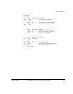
directive is specified differently (see AREA on page 7-52 and Examples on
page 7-51).


