


2-58
Cisco Aironet 1550 Series Outdoor Mesh Access Point Hardware Installation Guide
OL-24247-01
Chapter 2 Installing the Access Point
Powering the Access Point
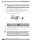
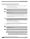
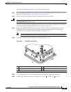
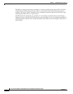
Figure 2-44 Inserting the Terminal Strip into the DC Power Opening in the Access Point Case
Step 9
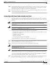
Slide the liquid-tight adapter towards the access point, and screw the threaded end of the adapter into the
access point, and hand-tighten.
Step 10 Use an adjustable wrench, a 22-mm socket, or a Sealcon S-2200-WR wrench to tighten the threaded end
of the adapter to 6 to 7 ft lbs (8.1 to 9.5 Nm).
Step 11 Use an adjustable or open-end wrench to tighten the round end of the adapter to 2.7 to 3.2 ft lbs (3.66 to
4.34 Nm).
Step 12 Ensure that the antennas are connected to the access point before you apply power to the access point.
Step 13 Turn on the DC power at the designated circuits.
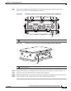
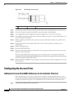
Connecting a Cable POC Power to the Access Point
The cable configuration on a 1552C or 1552CU access point contains a cable modem and RF splitter but
does not contain a cable stinger connector. The cable stinger connector is customer supplied.
Note To ensure system performance, with respect to immunity from external electromagnetic fields, the
installer must use a well shielded coax cable (quad shield).
Note The POC access point is classified as a type “Hazardous Voltage Secondary” circuit as per the
UL/IEC/EN 60950-1 safety standard. The cable distribution network used with this access point must
provide transient reduction to the level for this type of circuit classification (that is, 500V
transient/lightning surge).
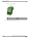
1 Two-position terminal strip 3 Liquid-tight adapter
2 DC power cable 4 DC power opening in access point case