


1-23
Cisco Aironet 1550 Series Outdoor Mesh Access Point Hardware Installation Guide
OL-24247-01
Chapter 1 Overview
Hardware Features
Note When a 1552E or 1552EU access point is powered by PoE, the PoE-Out port is not active.
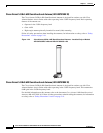
The access point PoE-out (10/100/1000BASE-T) port uses an RJ-45 connector to provide LAN
connectivity and IEEE 802.3af power to a single peripheral customer device, such as a camera or sensor
gateway. The PoE-out port should not be connected to a switch or hub. The Ethernet MAC addresses are
printed on the bottom of the access point under the LEDs.
Note The PoE-out port is disabled when the access point is powered by the power injector.
Tip The access point senses the Ethernet and power signals and automatically switches internal circuitry to
match the cable connections.
Warning
To reduce the risk of fire, use only No. 26 AWG or larger telecommunication line cord.
Statement 1023
The Ethernet cable must be a shielded outdoor rated Category 5e (CAT5e) or better cable. The access
point senses the Ethernet and power signals and automatically switches internal circuitry to match the
cable connections.
Caution To provide inline PoE, you must use the 1500 power injector (AIR-PWRINJ1500-2=). Other power
injectors, PoE switches, and 802.3af power sources cannot provide adequate power, which may cause
the access point to malfunction and cause possible over-current conditions at the power source.
Fiber Option
Warning
Class 1 laser product.
Statement 1008
The factory-orderable fiber option provides a fiber input and output capability. Fiber data is transmitted
and received over a single-strand fiber cable, which is connected to the access point using these SFP
modules:
• 100BASE-BX10-U fiber Rugged small-form factor pluggable (SFP) module
• 1000BASELX single-mode Rugged SFP module
• 1000BASESX multimode Rugged SFP module
• EPON ONU Rugged SFP module
Note SFP modules are not hot-swappable.
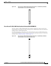
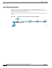
The access point has one fiber connection, located on the bottom of the unit (shown on Figure 1-1).
Client data is passed to the network controller through the fiber connection via a fiber-capable switch.
Configuration information can be found in the controller configuration guide of the controller you are
using.