


1-12
Cisco Aironet 1550 Series Outdoor Mesh Access Point Hardware Installation Guide
OL-24247-01
Chapter 1 Overview
Hardware Features
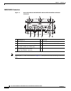
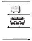
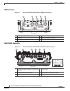
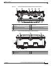
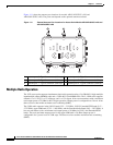
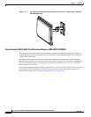
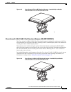
Figure 1-11 shows the antenna port locations for models AIR-CAP1552CU-x-K9 and
AIR-CAP1552EU-x-K9. The ports used depend on the optional antennas ordered.
Figure 1-11 External Antenna Port Locations for Access Point Models AIR-CAP1552CU-x-K9 and
AIR-CAP1552EU-x-K9
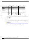
Multiple Radio Operation
The 1552 access point supports simultaneous dual-radio operation using a 2.4-GHz 802.11b/g/n multiple
input/multiple output (MIMO) radio and a 5-GHz 802.11a/n MIMO radio. The 2.4 GHz radio supports
channels 1 to 11 in US, 1 to 13 in Europe, and 1 to 13 in Japan. It has two transmitters with a maximum
total output power of 25 dBm for 802.11b/g/n operation. Output power is configurable to 5 levels. It has
three receivers that enable maximum-ratio combining (MRC).
The 5-GHz radio operates in the UNII-2 band (5.25 – 5.35 GHz), UNII-2 Extended/ETSI band (5.47 –
5.725 GHz), upper ISM band (5.725 – 5.850 GHz), and the Extended India Band (5.85 – 5.875 GHz). It
has two transmitters with a maximum total output power of 26 dBm for UNII-2 and Extended/ETSI
bands. The total maximum output power for the upper ISM band is 28 dBm. Output power is
configurable for 5 power levels in 3 dB steps. The three receivers enables maximum-ratio combining
(MRC).
1 Antenna port 3 - Type N connector (with cap) 4 Antenna port 6 - Type N connector (with cap)
2 Antenna port 2 - Type N connector (with cap) 5 Antenna port 5 - Type N connector (with cap)
3 Antenna port 1 - Type N connector (with cap) 6 Antenna port 4 - Type N connector (with cap)
345674
123
456