


2-10
Cisco Aironet 1550 Series Outdoor Mesh Access Point Hardware Installation Guide
OL-24247-01
Chapter 2 Installing the Access Point
Installation Guidelines
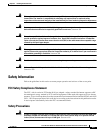
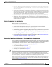
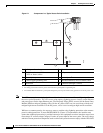
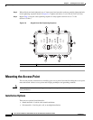
Figure 2-1 Components in a Typical Access Point Installation
Note The 1552 access point was designed with consideration for resistance to effects of lightning effects on
the access point electronics. The 1552 access point employs lightning arrestor circuitry on the Ethernet
and power ports. On the input Ethernet port, Gas Discharge Tubes (GDT) are used for the Power Entry
Module (PEM) to mitigate lightning effect. On the AC power, GDTs are also used along with fuses to
mitigate high-current condition. For the DC power, a fuse is used to mitigate high current condition.
While not a common practice, the user may want to consider using lightning protection at the antenna
ports for added protection. To meet EN/IEC60950-22 (Clause 4.2) requirements, the installer must
ensure that additional protection is provided external to this equipment to reduce transient surges from
Overvoltage IV to Overvoltage Category II at the AC power input of the access point. The over-voltage
and fault-current protection components used to achieve this protection must comply with the IEC 61643
1 Building roof-overhang 6 Ground
2 Shielded outdoor-rated Ethernet
(CAT5e or better) cable
1
1. User supplied.
7 AC power cord
2
2. The safety ground wire in the AC power cord must have a ground path to a grounding rod.
3 Water drip loop 8 Power injector
3
3. The shielded Ethernet cable has a ground path through the power injector and the safety ground wire in the AC power cord.
4 6-AWG copper grounding wire
1
9 Shielded Ethernet (CAT5e or better) cable
1
5 Ground rod
1
10 Controller (through a switch)
281938
1
10 8
9
7
6
5
4
3
2