


2-59
Cisco Aironet 1550 Series Outdoor Mesh Access Point Hardware Installation Guide
OL-24247-01
Chapter 2 Installing the Access Point
Powering the Access Point
To connect cable POC power to the access point, follow these steps:
Step 1 Before connecting cable POC power to the access point, ensure that the ground is connected to the access
point (see the “Grounding the Access Point” section on page 2-41).
Step 2 Ensure that all power sources have been disconnected from the access point.
Warning
This unit might have more than one power supply connection. All connections must be removed to
de-energize the unit.
Statement 1028
If your access point contains a backup battery pack, you must press the reset button for 10 seconds or
more (see the “Disabling Backup Battery Power” section on page 3-10).
Step 3 Remove the ATTN and SHUNT connector plugs on the top of the access point. Follow your cable
company procedures to measure the cable signal strength and possibly adjust signal attenuation
externally to the access point or on the RF splitter (see Figure 2-45).
Note The cable modem MAC address is located on the bottom of the access point under the LEDs.
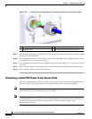
Step 4 Locate the F-connector adapter on the access point (see Figure 2-45).
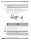
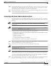
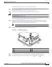
Figure 2-45 RF Splitter Components
Step 5 Use a Phillips screw driver to loosen the pin capture screw, but be careful not to remove it.
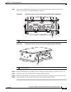
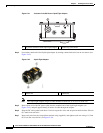
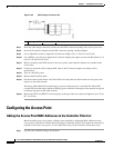
Step 6 Cut the cable stinger connector pin (see Figure 2-46) to 0.75 + 0.1 inch (1.91 + 0.25 cm).
1 RF splitter attenuator (ATTN) 2 RF splitter shunt (SHUNT)
1
3 F-connector adapter (stinger connector pin)
1
Shunt is a 20 amp fuse.
3
1
2
255265