


2-60
Cisco Aironet 1550 Series Outdoor Mesh Access Point Hardware Installation Guide
OL-24247-01
Chapter 2 Installing the Access Point
Configuring the Access Point
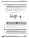
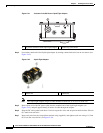
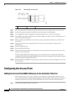
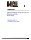
Figure 2-46 Cable Stinger Connector Pin
Step 7
Insert the cable stinger connector pin into the cable POC connector opening in the access point case.
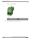
Step 8 Screw the F-connector adapter into the POC connector opening, and hand-tighten.
Step 9 Use an adjustable wrench to tighten the F-connector adapter to 6 to 7 ft lbs (8.1 to 9.5 Nm).
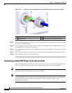
Step 10 Use a Phillips screw driver to tighten the F-connector adapter pin capture screw on the RF splitter to 5.5
to 6.0 in. lbs (0.62 to 0.67 Nm).
Step 11 Before connecting cable POC power to the access point, ensure that the antennas are attached to the
access point.
Step 12 Connect or attach the cable company POC cable to the F-connector adapter according to their
specifications.
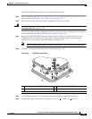
Step 13 Turn on cable POC power.
Step 14 Reinsert the RF splitter shunt.
Step 15 Check the cable modem Power and Cable LEDs and verify that the cable modem receives power and
registers to the cable network.
The Power LED (fifth LED from the hinge) is green to indicate power is available.The Cable LED
(second LED from the hinge) should be blinking green to indicate scanning the cable network and green
to indicate registered on the cable network.
Step 16 Replace the ATTN and SHUNT connector plugs on the top of the access point and tighten to 6 to 7 ft lbs
(8.1 to 9.5 Nm).
Configuring the Access Point
Adding the Access Point MAC Addresses to the Controller Filter List
Before installing your access points, configure your controller by adding the MAC addresses of the
access points to the filter list. MAC address filtering is enabled by default. This enables the controller to
respond to the listed access points. To add a MAC filter entry on the controller, follow these steps:
Step 1 Log into your controller using a web browser.
1 Pin length is 0.75 +
0.1 inch (1.91 + 0.25 cm).