


2-32
Cisco Aironet 1550 Series Outdoor Mesh Access Point Hardware Installation Guide
OL-24247-01
Chapter 2 Installing the Access Point
Mounting the Access Point
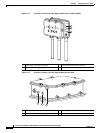
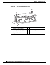
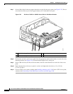
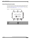
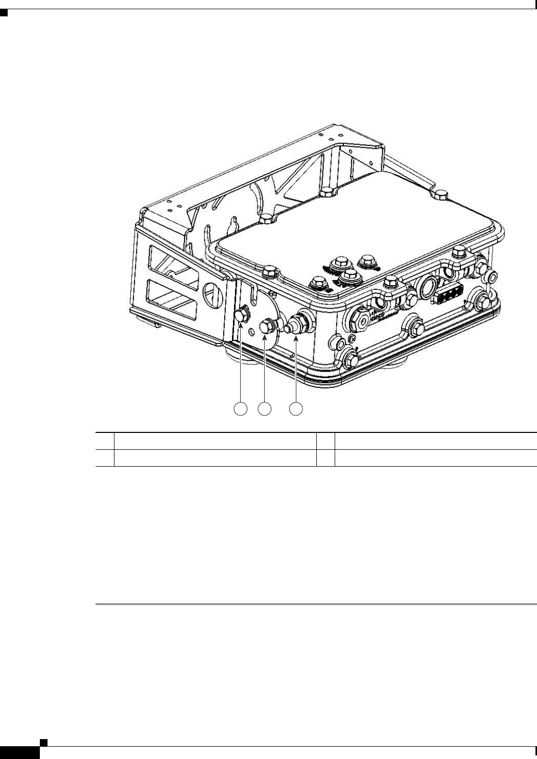
Step 7 Screw a M8 x16 bolt in the top support bolt hole on each side the access point (see Figure 2-22). Do not
screw the bolt all the way in; leave approximately a 0.25 inch (0.635 cm) space.
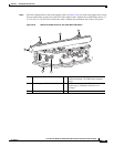
Figure 2-22 Position of 1552C or 1552CU Access Point in Pole Mount Bracket
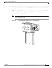
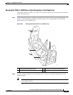
Step 8
Position the two bolts on the access point into the appropriate quick mount notches on each side of the
mounting bracket (see Figure 2-22). Ensure that the hinged door is facing out.
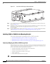
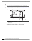
Step 9 Screw a M8 x16 bolt (with flat and lock washers) into the second bolt hole on each side of the access
point.
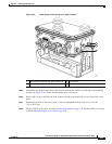
Step 10 Ensure that the front of the access point is vertical, and tighten the four bolts to 13 to 15 ft lbs
(17.6 to 20.3 Nm).
Step 11 For the 1552CU access point, continue with Installing Antennas, page 2-36. For the 1552C access point,
continue with Connecting a Cable POC Power to the Access Point, page 2-58.
1 M8 x16 bolt (supplied with pole mount kit) 3 F-connector
2 M8 x16 bolt (supplied with pole mount kit)
1 2 3
331579