


1-6
Cisco Aironet 1550 Series Outdoor Mesh Access Point Hardware Installation Guide
OL-24247-01
Chapter 1 Overview
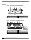
Hardware Features
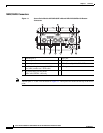
1552E/1552EU Connectors
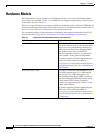
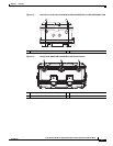
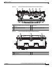
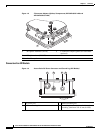
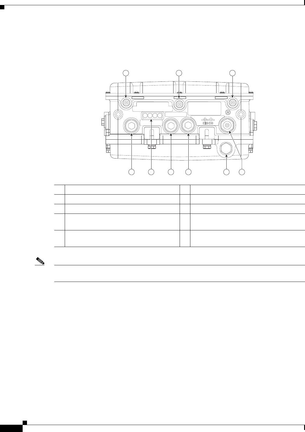
Figure 1-1 Access Point Models AIR-CAP1552E-x-K9 and AIR-CAP1552EU-x-K9 Bottom
Connectors
Note Antenna ports 1, 2, and 3 are not shown in Figure 1-1. These ports are located on the top of the access
point.
1 Antenna port 4 6 Fiber port
2 Antenna port 5 7 PoE-out port
3 Antenna port 6 8 LEDs (Status, Up Link, RF1, RF2)
4 Auxiliary cable gland entry (1/2-NPT) for
data cable (outdoor cat 5 STP cable)
9 PoE-in port
5 AC power entry port for model
AIR-CAP1552E/EU-x-K9 only
45 6
282137
1 2 3
45
6
789