


2-40
Cisco Aironet 1550 Series Outdoor Mesh Access Point Hardware Installation Guide
OL-24247-01
Chapter 2 Installing the Access Point
Installing Antennas
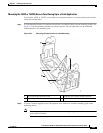
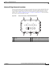
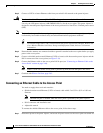
The AIR-CAP1552E-x-K9 model can be operated in either of the configurations shown below. In
addition, it can be operated with one directional antenna installed for one frequency band and three
omnidirectional “stick” antennas installed for the other frequency band.
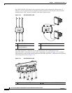
Figure 2-30 AIR-CAP1552EU-x-K9
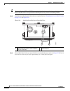
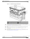
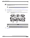
The AIR-CAP1552CU-x-K9 model can be operated with the same configurations as the
AIR-CAP1552EU-x-K9 model on a pole mount configuration, as shown in Figure 2-30. In addition,
when installed in a cable strand mount configuration, the AIR-CAP1552CU-x-K9 model can be operated
with configuration shown in Figure 2-31.
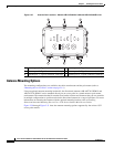
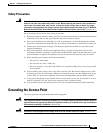
Figure 2-31 AIR-CAP1552CU-x-K9
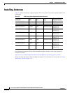
1 AIR-ANT5180V-N 1 AIR-ANT5114P2M-N
2 AIR-ANT2450V-N or
AIR-ANT2480V-N
2 AIR-ANT2413P2M-N
1
2
345763
2.4 GHz
5 GHz
345741
1 1 1
2 2 2
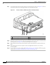
1 5-GHz antenna AIR-ANT5140V-N 2 2.4-GHz antenna AIR-ANT2420V-N
2
1
345761