


2-23
Cisco Aironet 1550 Series Outdoor Mesh Access Point Hardware Installation Guide
OL-24247-01
Chapter 2 Installing the Access Point
Mounting the Access Point
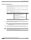
Step 8 Install four M8 x16 bolts (with flat and lock washers) into the bolt holes.
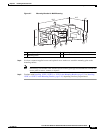
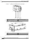
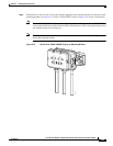
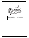
Figure 2-12 Screw Hole Locations on the Mounting Bracket and Pole Clamp Bracket Assembly
Step 9 Hand-tighten the bolts and the nut (do not overtighten).
Step 10 Adjust the top edge of the mounting bracket until it is horizontal and tighten the bolts and the flange nut
(see Figure 2-12) to 13 to 15 ft lbs (17.6 to 20.3 Nm).
Note The mounting bracket can be adjusted up to 45
o
to compensate for tilted horizontal streetlight
poles.
Step 11 Continue with Installing 1552E, 1552EU, or 1552I in the Mounting Bracket, page 2-23 or Installing
1552C or 1552CU in the Mounting Bracket, page 2-26, depending on what you purchased.
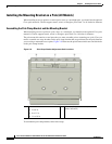
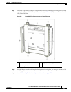
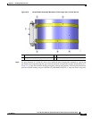
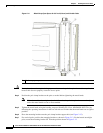
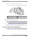
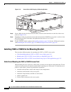
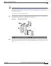
Installing 1552E, 1552EU, or 1552I in the Mounting Bracket
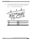
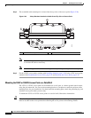
Step 1 Screw a M8 x16 bolt (without a flat or lock washer) in the top support bolt hole on each side of the access
point (see Figure 2-13 or Figure 2-14, depending on what you purchased). These bolts are supplied with
pole mount kit. Do not screw the bolt all the way in. Leave a gap of approximately 0.25 inch (0.635 cm).
1 Pole clamp bracket assembly 3 Bolt holes
2 Access point support bolt
(M8 flange nut not shown)
4 Mounting bracket
281940
1
2
3
4
3
3