


E-2
Cisco Aironet 1550 Series Outdoor Mesh Access Point Hardware Installation Guide
OL-24247-01
Appendix E Access Point Pinouts
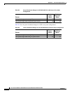
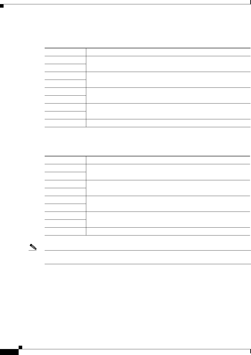
Table E-3 describes the pin signals for the power injector input connector (To Switch).
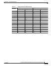
Table E-4 describes the RJ-45 pin signals for the power injector output connector (To AP).
Note The power injector output connector (To AP) only supplies 56 VDC power when the Ethernet cable is
connected to the 1550 PoE-in connector.
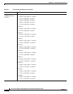
Table E-3 Power Injector Input Connector (To Switch) Pinouts
Pin Number Signal Name
1 Ethernet signal pair (10/100/1000BASE-T)
2
3 Ethernet signal pair 10/100/1000BASE-T)
6
4 Ethernet signal pair (1000BASE-T)
5
7 Ethernet signal pair (1000BASE-T)
8
Shield Chassis ground
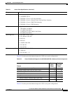
Table E-4 Power Injector Output Connector (To AP) Pinouts
Pin Number Signal Name
1 Ethernet signal pair (10/100/1000BASE-T) and 56 VDC return
2
3 Ethernet signal pair (10/100/1000BASE-T) and 56 VDC (+)
6
4 Ethernet signal pair (1000BASE-T) and 56 VDC (+)
5
7 Ethernet signal pair (1000BASE-T) and 56 VDC return
8
Shield Chassis ground