


2-38
Cisco Aironet 1550 Series Outdoor Mesh Access Point Hardware Installation Guide
OL-24247-01
Chapter 2 Installing the Access Point
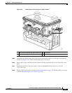
Installing Antennas
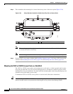
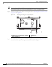
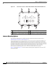
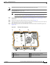
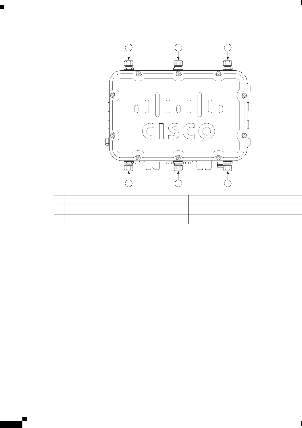
Figure 2-27 Antenna Port Locations - Models AIR-CAP1552CU-x-K9 and AIR-CAP1552EU-x-K9
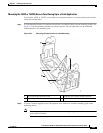
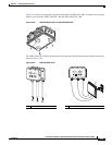
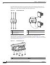
Antenna Mounting Options
Two mounting configurations are available, the cable strand mount and the pole mount (refer to
“Mounting the Access Point” section on page 2-14.)
Using an optional antenna mounting bracket kit, the directional antennas AIR-ANT2413P2M-N and
AIR-ANT5114P2M-N can be mounted directly on an access point in a strand mount or pole mount
environment. The antenna bracket kit contains four bracket sections and fasteners that you can assemble
in multiple configurations to position and aim the directional antenna in a range of positions. For more
information on mounting the antenna with the optional mounting bracket, refer to Installing
Directional-Antenna Mounting Kits on Cisco 1550 Series Outdoor Mesh Access Points.
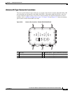
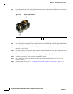
Figure 2-28 through Figure 2-31 show the antenna mounting options supported by the various 1552
access point models.
1 Antenna port 3 - Type N connector (with cap) 4 Antenna port 6 - Type N connector (with cap)
2 Antenna port 2 - Type N connector (with cap) 5 Antenna port 5 - Type N connector (with cap)
3 Antenna port 1 - Type N connector (with cap) 6 Antenna port 4 - Type N connector (with cap)
345674
123
456