


3-6
Cisco Aironet 1550 Series Outdoor Mesh Access Point Hardware Installation Guide
OL-24247-01
Chapter 3 Troubleshooting
Changing the Bridge Group Name
Changing the Bridge Group Name
The bridge group name (BGN) controls the association of the access points to a RAP. BGNs can be used
to logically group the radios to avoid different networks on the same channel from communicating with
each other. This setting is also useful if you have more than one RAP in your network in the same area.
If you have two RAPs in your network in the same area (for more capacity), we recommend that you
configure the two RAPs with different BGNs and on different channels.
The BGN is a string of ten characters maximum. A factory-set bridge group name (NULL VALUE) is
assigned during manufacturing. It is not visible to you, but allows new access point radios to join a
network of new access points. The BGN can be reconfigured from the Controller CLI and GUI. After
configuring the BGN, the access point reboots.
After the access points are deployed and associated to the controller, the BGN should be changed from
the default value to prevent the MAPs from attempting to associate to other mesh networks.
The BGN should be configured very carefully on a live network. You should always start with the most
distant access point (last node) from the RAP and move towards the RAP. If you start configuring the
BGN in a different location, then the access points beyond this point (farther away) are dropped, as they
have a different BGN.
To configure the BGN for the access points using the controller GUI, follow these steps:
Step 1 Log into your controller using a web browser.
Step 2 Click Wireless. When access points associates to the controller, the access point name appears in the AP
Name list.
Step 3 Click on an access point name.
Step 4 Find the Mesh Information section, and enter the new BGN in the Bridge Group Name field.
Step 5 Click Apply.
Step 6 Repeat Steps 2 through 5 for each access point.
Step 7 Log out from your controller, and close your web browser.
Connecting to the Access Point Locally
If you need to monitor the access point locally (without connecting the access point to a wired LAN),
you can connect a PC to its console port using a DB-9 to RJ-45 serial cable.
Note The console port should only be used for debugging in a lab environment.
Follow these steps to open the CLI by connecting to the access point console port:
Step 1 Open the hinged cover of the access point (see “Opening the Access Point Hinged Cover” section on
page 2-13 for instructions).
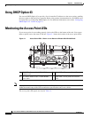
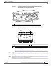
Connect a nine-pin, female DB-9 to RJ-45 serial cable to the RJ-45 console port on the access point and
to the COM port on a computer (see Figure 3-2 and Figure 3-3 for the console port locations).