


3-267
Cisco Signaling Gateway Manager User Guide
78-15589-01
Chapter 3 Managing ITP Networks Using SGM
Viewing the Topology of the Network
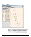
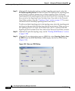
Step 19 (Optional) To display detailed information about an element in the map,
double-click it, then respond to SGM’s prompts:
• Double-click a signaling point to display the Details Window for that
signaling point.
• Double-click a single line, or a diamond or circle at the end of a single line,
to display the Linkset Details Window for that linkset.
• Double-click a heavy line, or a diamond or circle at the end of a heavy line,
to display the Selection Dialog. Then select one of the linksets to display the
Linkset Details Window for that linkset.
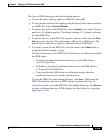
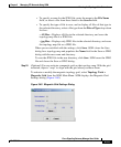
Step 20 (Optional) To display the topology new signaling point panel, select the New
Signaling Points tab in the left pane. The topology new signaling point panel
displays graphical elements for newly discovered signaling points, based on the
following criteria:
• If you are using an SGM client with the DEFAULT view set, this panel never
contains any signaling points. In the DEFAULT view, SGM adds all newly
discovered signaling points to the topology map as soon as they are
discovered.
• If you are using an SGM client with a custom view set, this panel contains all
signaling points discovered since the Topology window was opened in this
session that have not been excluded in the Signaling Points Excluded from
View table of the Network View Editor window, or that are not in the current
view.
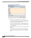
a. (Optional) To add a newly discovered signaling point to the topology map,
select one or more signaling points in the topology new signaling point panel
and drag them to the map while holding down the left mouse button.
b. (Optional) To exclude a newly discovered signaling point from the topology
new signaling point panel, see the “Working with Views” section on
page 3-26.