


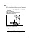
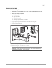
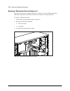
3-22 Removal and Replacement Procedures
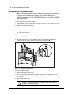
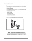
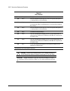
Table 3-2
Drive Positions
Reference Component Description
1 Bay 1 Part of the removable hard drive cage. A 3.5-inch, third-height bay that supports a
1.0-inch hard drive or a 1.6-inch hard drive.
2 Bay 2 Part of the removable hard drive cage. A 3.5-inch, third-height bay that supports a
1.0-inch hard drive. Bay 2 is not available when a 1.6-inch hard drive is installed in
Bay 1 or Bay 3.
3 Bay 3 Part of the removable hard drive cage. A 3.5-inch, third-height bay that supports a
1.0-inch hard drive or a 1.6-inch hard drive.
4 Bay 4 A CD-ROM drive is shipped in Bay 4.
5 Bay 5* 5.25-inch, half-height bay that supports 1.0-inch or 1.6-inch storage devices. An
optional hard drive, diskette drive, CD-ROM drive, DVD-ROM drive, or tape drive can
be installed in Bay 5.
6 Bay 6* 5.25-inch, half-height bay that supports 1.0-inch or 1.6-inch storage devices. An
optional hard drive, diskette drive, CD-ROM drive, DVD-ROM drive, or tape drive can
be installed in Bay 6.
7 Bay 7 3.5-inch, third-height bay that supports a 1.0-inch device. A standard 3.5-inch
diskette drive is shipped in Bay 7.
* An additional Zip drive can be installed in these bays.
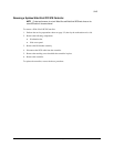
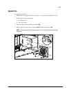
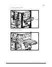
CAUTION: If a hard drive is installed in Bay 5 or 6 or if the bays are empty, be
sure that EMI/cooling shields are installed to ensure proper air flow and cooling.
IMPORTANT: Compaq recommends 10,000 rpm hard drives be installed first in Bays 1, 2,
or 3. Installing a 10,000 rpm hard drive in Bays 5 or 6 will require an additional cooling fan
kit.