


Introduction 1-1
Chapter 1
Introduction
D
ell
®
PowerEdge
™
4100/180 and Dell Power-
Edge 4100/200 systems are high-speed, upgradable
servers that offer a number of significant service and
upgrade features.
The Dell PowerEdge 4100 systems’ service features
make troubleshooting easy and effective. Every system
includes CD-based Dell diagnostics software for diag-
nosing system problems if the system can boot. The
embedded server management hardware monitors tem-
peratures and voltages throughout the system and notifies
you if the system overheats or if one of the system cool-
ing fans malfunctions. If the system has an optional
power-supply paralleling board and redundant power
supplies, the server management hardware also monitors
the status of the power supplies.
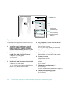
The Dell PowerEdge 4100 system chassis simplifies
removing and replacing computer components. Processor
and memory upgrades can be performed without remov-
ing the system board. The Dell-designed small computer
system interface (SCSI) backplane board and hard-disk
drive carriers eliminate the extensive cabling and drive
configuration usually required for a SCSI subsystem. The
plastic drive rails attached to devices mounted in the
external drive bays allow you to remove devices without
removing a single screw.
Among the many upgrade options offered for the Dell
PowerEdge 4100 systems are a secondary micro-
processor, additional main memory, a variety of
expansion-card options (including the Dell PowerEdge
Expandable RAID Controller host adapter), and addi-
tional SCSI CD-ROM, tape, and hard-disk drives.
A
bout This Guide
This guide provides directions for trained service
technicians who are installing system options or are
troubleshooting problems that have temporarily disabled
a Dell PowerEdge system. Before calling for technical
assistance, follow the recommended procedure(s) in this
guide to solve most hardware and software problems
yourself.
•
Chapter 2, “Checking the Basics,” outlines some ini-
tial checks and procedures and also directs you to the
appropriate chapter in this guide for more detailed
troubleshooting information.
•
Whenever you receive an error message or code, you
should read Chapter 3, “Messages and Codes.”
•
If you suspect that the problems are software-related,
or you are still having problems after testing the
computer’s hardware, read Chapter 4, “Finding Soft-
ware Solutions.”
•
For hardware-related problems, read Chapter 5,
“Running the System Diagnostics.” Chapter 6,
“Checking the Equipment,” and Chapter 7, “Check-
ing Inside the Computer,” provide troubleshooting
procedures for equipment connected to the input/
output (I/O) panel of the computer and components
inside the computer, respectively.
Chapter 7 also provides information on removing the
computer covers and front bezel.
•
If you are installing or removing system options, such
as dual in-line memory modules (DIMMs), expansion
cards, or SCSI devices, refer to Chapter 8, “Installing
System Board Options,” Chapter 9, “Installing Drives
in the External Bays,” or Chapter 10, “Installing
Drives in the Internal Bays.”