


Installing System Board Options 8-9
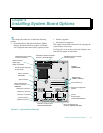
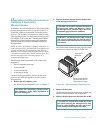
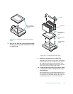
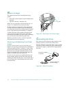
Figure 8-9. Installing the Microprocessor
Chip
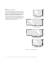
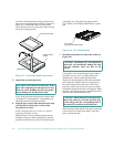
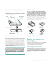
8. Place the new heat sink (with its bonded thermal
interface pad) on top of the microprocessor chip
(see Figure 8-10).
Figure 8-10. Installing the Heat Sink
9. Replace the microprocessor securing clip.
Orient the clip as shown in Figure 8-10, and hook the
unfolded end of the clip over the tab on the edge of
the socket facing the front of the computer. Then
press down on the folded end of the clip to snap the
clip over the tab on the back of the socket.
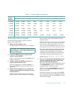
10. Change the microprocessor-speed jumper setting
to correspond to the new microprocessor’s oper-
ating frequency.
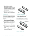
The microprocessor’s speed jumper should be set for
the installed microprocessor’s rated internal speed.
For example, for a 200-MHz Pentium Pro processor,
a jumper plug should be installed on the jumper
pin-1 corners of
chip and socket
aligned
heat sink
microprocessor
chip
microprocessor
socket
clip
thermal pad
(bonded to heat
sink)