


8-4 Dell PowerEdge 4100/180 and 4100/200 Systems Installation and Troubleshooting Guide
Configuration Utility and delete the expansion
card from the configuration.
See Chapter 5, “Using the EISA Configuration Util-
ity,” in the system User’s Guide for instructions.
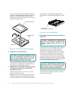
2. Remove the left computer cover.
See “Removing the Computer Covers” in Chapter 7.
3. If necessary, disconnect any cables connected to
the card.
4. Unscrew the card-mounting bracket.
If the expansion card is full-length, release the lock-
ing cam on the card guide.
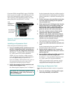
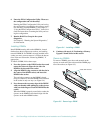
5. Grasp the card by its top corners, and ease it out
of its connector.
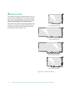
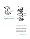
6. If you are removing the card permanently, install
a metal filler bracket over the empty card-slot
opening.
NOTE: Installing a filler bracket over an empty
expansion slot is necessary to maintain Federal
Communications Commission (FCC) certification of
the system. The brackets also keep dust and dirt out
of the computer and aid in proper cooling and air-
flow inside the computer.
7. Replace the left computer cover, reconnect the
computer and peripherals to their power sources,
and turn them on.
8. If you are relocating or removing an EISA expan-
sion card, start the EISA Configuration Utility,
and delete the expansion card from the configura-
tion information.
See Chapter 5, “Using the EISA Configuration Util-
ity,” in the system User’s Guide for instructions.
NOTE: If you removed a PCI expansion card, the
system automatically performs any required re-
configuration tasks during the boot routine.
A
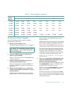
dding Memory
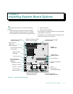
The eight dual in-line memory module (DIMM) sockets on
the system board can accommodate 64 to 1024 megabytes
(MB) of dynamic random-access memory (DRAM). The
Dell PowerEdge 4100 systems use 72-bit, buffered,
extended-data out (EDO) DIMMs in these 168-pin sock-
ets. The DIMM sockets are located near the right edge of
the system board (see Figure 8-1).
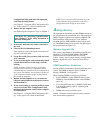
Memory Upgrade Kits
The system is upgradable to 1024 MB by installing com-
binations of 32- and 128-MB DIMMs. The DIMMs
should be rated at 60 nanoseconds (ns) or faster.
Table 8-1 shows several sample memory configurations.
Memory upgrade kits can be purchased from Dell as
needed.
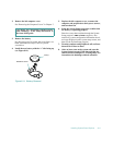
DIMM Installation Guidelines
Starting with the socket farthest from the microprocessor
sockets, the DIMM sockets are labeled “DIMM A”
through “DIMM H” (see Figure 8-1).
When installing DIMMs, follow these guidelines:
•
Install a DIMM in socket DIMM A before socket
DIMM B, socket DIMM B before socket DIMM C,
and so on.
•
If you install different sizes of DIMMs, install them
in order of descending capacity, beginning with
socket DIMM A.
•
DIMMs need not be installed in pairs.
Table 8-1 illustrates several sample memory configura-
tions based on these guidelines.
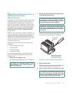
CAUTION: See “Protecting Against Electro-
static Discharge” in the safety instructions at
the front of this guide.