


Checking Inside the Computer 7-9
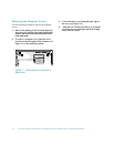
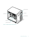
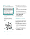
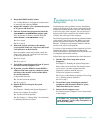
4. Slide the power supply out of the chassis (see Fig-
ure 7-7).
Figure 7-7. Removing the Power Supply
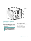
5. Check that the locking switch on the new power
supply is set to the “off” position, then slide the
power supply into the chassis.
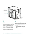
6. Turn the locking knob clockwise until the replace-
ment power supply is secured in the chassis.
7. Connect the AC power cable to the power supply
and to the power outlet.
Make sure that the AC power cable passes through
the plastic strain-relief clip.
8. Turn the locking switch on the power supply to
the “on” position, marked by an “I.”
If an optional power-supply paralleling board is
installed, the green online indicator on the power
supply should light up.
Troubleshooting Power Cable
Connections
1. Check the AC power outlet and power cable (see
“Checking Connections and Switches” in Chap-
ter 2.
2. Turn off the system, including any attached
peripherals, and disconnect all the AC power
cables from their power sources.
3. Remove the computer covers.
See “Removing the Computer Covers” found earlier
in this chapter.
4. Check the cable connections listed in Table 7-1.
.
T
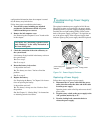
roubleshooting a Cooling Fan
Three cooling fans are installed in the Dell PowerEdge
4100 system. Two fans are used to cool the computer; the
third cooling fan does not operate unless one of the other
two fans fails. If you observe that only one of the three
redundant cooling fans is operating, or the Dell HIP
server-management application program issues a fan-
related error message, replace the fan as described in the
following subsection.
Table 7-1. Power Cable Connectors on the
Optional Power-Supply Paralleling Board
Connector Cable Connection
PWR1 To POWER1 connector on
system board
PWR2 To POWER2 connector on
system board
PWR3 To POWER3 connector on
system board
PWRFD To diskette drives and other
devices in external drive
bays
PWRSCSI To POWER connector on
SCSI backplane