


C-4 Dell PowerEdge 4100/180 and 4100/200 Systems Installation and Troubleshooting Guide
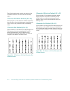
S
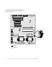
ystem Board Labels
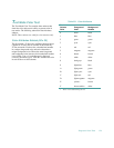
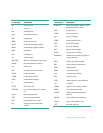
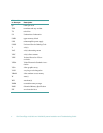
Table C-2 lists the connectors and sockets located on the
system board. Table C-3 lists the connectors on the SCSI
backplane board.
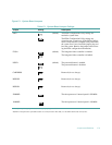
Table C-1. System-Board Jumper Settings
Jumper Setting Description
jumpered
unjumpered
Table C-2. System Board Connectors and Sockets
Connector or Socket Description
BATTERY Battery connector
DIMM x DIMM socket
EISAn EISA expansion-card connector
FANn Fan connector
FLOPPY Diskette/tape drive interface connector
KEYBOARD Keyboard connector
MONITOR Video connector
MOUSE Mouse connector
PARALLEL Parallel port connector; sometimes referred to as LPT1
PCIn PCI expansion-card connector
POWERn Power input connector
PROCESSOR1 Microprocessor socket
PROCESSOR2 Microprocessor socket
REMOTE Server-management serial port connector
SCSI CD-ROM Ultra/Narrow SCSI host adapter connector
SCSI BACKPLANE Ultra/Wide SCSI host adapter connector
SERIALn Serial port connector; sometimes referred to as COM1 and COM2
SMB BACKPLANE Server-management bus connector