


Installing Drives in the External Bays 9-3
The power connectors are keyed to avoid incorrect inser-
tion; do not force two connectors together if they do not
fit properly.
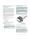
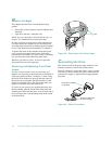
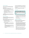
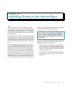
A ribbon cable (see Figure 9-4) functions as the interface
cable for most types of drives.
Figure 9-4. Header Connector
Most interface connectors are keyed for correct insertion;
that is, a notch or a missing pin on one connector matches
a tab or a filled-in hole on the other connector. Keying
ensures that the pin-1 wire in the cable (indicated by the
colored strip along one edge of the cable) goes to the
pin-1 ends of the connectors on both ends. A header con-
nector is usually keyed by the omission of one of its pins
with the corresponding hole filled in on the connector on
the cable (see Figure 9-4).
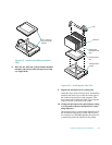
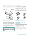
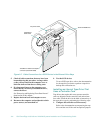
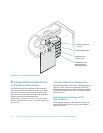
DC Power Cables
Each drive in the external drive bays must connect to a
4-wire DC power cable from the system power supply or
optional power-supply paralleling board. The connectors
on this cable are labeled “FD1,” “FD2,” “FD3,” “FD4,”
and “FD5.” Connectors FD1 through FD4 are used for
5.25-inch devices, whereas connector FD5 is used for the
standard 3.5-inch diskette drive. Before connecting a
drive to a power cable, refer to Figure 9-5 to identify the
correct cable connector to use for the drive.
Figure 9-5. DC Power Cable Connectors
I
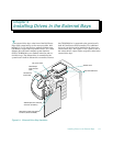
nstalling SCSI Devices in the
External Bays
SCSI devices in the external drive bay (such as CD-ROM
drives and tape drives) are controlled by the Ultra/
Narrow SCSI controller on the system board.
SCSI Configuration Information
Although SCSI devices are installed essentially the same
way as other devices, their configuration requirements
are different. To configure SCSI devices installed in the
external bays, follow the guidelines in the following
subsections.
CAUTION: When connecting an interface cable,
do not reverse the interface cable (do not place the
colored strip away from pin 1 of the connector).
Reversing the cable prevents the drive from oper-
ating and could damage the controller, the drive,
or both.
key (cut-off pin)
key
(blocked hole)
header connector
interface connector
pull tab
colored strip on
ribbon cable
system board
connector
5.25-inch drive
connector
3.5-inch drive
connector
system board
connector