


Installing Drives in the Internal Bays 10-5
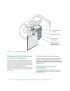
2. Remove the computer cover.
See “Removing the Computer Covers” in Chapter 7.
3. Remove the Ultra/Wide SCSI cable from the
computer.
•
One end of the cable attaches to the SCSI host
adapter connector labeled “SCSI BACK-
PLANE” on the system board.
•
The cable’s other end attaches to the connector
labeled “SCSI” on the SCSI backplane board.
4. Install the PowerEdge Expandable RAID Con-
troller host adapter card in one of the peripheral
component interconnect (PCI) expansion slots.
See “Installing an Expansion Card” in Chapter 8.
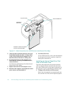
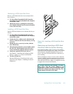
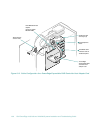
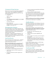
5. Connect the new Ultra/Wide SCSI cable provided
in the PowerEdge Expandable RAID Controller
kit to the connector labeled “SCSI” on the SCSI
backplane board (see Figure 10-3).
6. Connect the other end of the SCSI cable to the
PowerEdge Expandable RAID Controller host
adapter card.
To identify the correct connector, refer to documen-
tation for the PowerEdge Expandable RAID
Controller host adapter card.
NOTES: If you will be attaching external SCSI devices
using the external SCSI connection slots on the com-
puter’s back panel, follow steps 7 through 10.
If SCSI devices are connected using the external SCSI
connection slots, Ultra SCSI mode is not supported.
7. Connect the SCSI external access cable from the
host adapter kit to the Ultra/Wide SCSI host
adapter connector (labeled “SCSI BACK-
PLANE”) on the system board.
See the documentation that came with each device
for information on cabling that device as part of a
daisy chain.
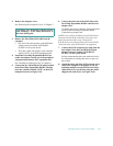
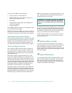
8. Attach the other end of the SCSI external access
cable to the computer’s back panel. If you are
attaching multiple external SCSI devices, daisy-
chain the devices to each other using the cables
shipped with each device (see Figure 10-4).
CAUTION: See “Protecting Against Electro-
static Discharge” in the safety instructions at
the front of this guide.