


Installing Drives in the External Bays 9-7
or switches that must be set to work with the system,
verify or change the settings as necessary.
2. Remove the computer covers and front bezel.
See “Removing the Computer Covers” and “Remov-
ing the Front Bezel” in Chapter 7.
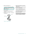
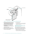
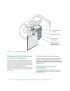
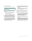
3. Slide the new drive into its bay until it snaps
securely into place.
If necessary, you can adjust drive alignment by
repositioning one or both rails.
4. Install the controller card in an expansion slot.
See “Installing an Expansion Card” in Chapter 8.
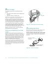
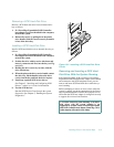
5. Connect a DC power cable to the tape drive.
If other installed drives are in the way, disengage
them by pressing in on the plastic drive rails at the
front of the bay, and slide them slightly toward the
front of the chassis.
Refer to “DC Power Cables” found earlier in this
chapter to determine which DC power cable connec-
tor to use. Plug the DC power cable connector into
the 4-pin power input connector on the back of the
drive.
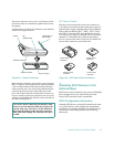
6. Attach the interface cable that came with the
drive kit to the card-edge connector on the back
of the drive.
7. Route the other end of the interface cable through
a cutout in the center wall of the chassis to the
controller card, and connect the interface cable to
the controller connector on the card.
Refer to the controller card’s documentation to iden-
tify the controller connector on the card.
8. If you moved other drives in step 5, snap them
back into place.
9. Check all cable connections that may have been
loosened during this procedure. Arrange cables
so they will not catch on the computer cover or
block the airflow of the fans or cooling vents.
10. If a front-panel insert on the computer cover
blocks the bay in which you installed the drive,
remove the insert.
See “Removing and Replacing Front-Panel Inserts”
found earlier in this chapter.
11. Replace the computer bezel and covers.
12. Reconnect the computer and peripherals to their
power sources, and turn them on.
13. Perform a tape backup and verification test with
the drive as instructed in the tape-drive software
documentation that came with the drive.
If the controller card is an ISA or EISA expansion
card, run the EISA Configuration Utility and update
the system configuration. See Chapter 5, “Using the
EISA Configuration Utility,” in the User’s Guide for
instructions on running the utility and saving the
configuration information.
NOTE: You do not need to update the system configuration
information for a tape drive attached to its own controller
card.
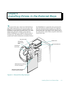
I
nstalling an External Tape Drive That
Uses a Controller Card
Complete the following procedure to install an external
tape drive that uses a controller card and shielded inter-
face/DC power cable:
1. Prepare the tape drive and controller card for
installation.
Ground yourself by touching an unpainted metal sur-
face on the back of the computer. Unpack the tape
drive and controller card, and configure them for the
system according to the instructions in the documen-
tation that came with the tape drive.
2. Remove the left computer cover.
See “Removing the Computer Covers” in Chapter 7.
CAUTION: See “Protecting Against Electro-
static Discharge” in the safety instructions at
the front of this guide.
CAUTION: See “Protecting Against Electro-
static Discharge” in the safety instructions at
the front of this guide.