


Installing System Board Options 8-5
Performing a Memory Upgrade
Use the following procedure to perform a memory
upgrade to the system board:
1. Remove the left computer cover.
See “Removing the Computer Covers” in Chapter 7.
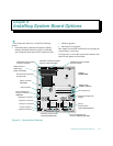
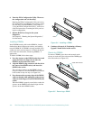
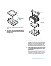
2. Locate the DIMM sockets in which you will
install or replace DIMMs.
Figure 8-1 shows the location of the DIMM sockets
on the system board.
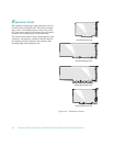
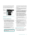
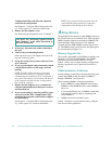
3. Install or replace the DIMMs as necessary to
reach the desired memory total.
Follow the instructions in “Installing DIMMs” or
“Removing DIMMs” found later in this section, as
appropriate.
4. Replace the left computer cover, reconnect the
computer and peripherals to their power sources,
and turn them on.
After the system completes the power-on self-test
(POST) routine, it runs a memory test that displays
the new memory total, which includes all newly
installed memory.
NOTE: If the memory total is incorrect, turn off and
disconnect the computer and peripherals from their
power sources, remove the computer cover, and
check all the installed DIMMs to make sure they are
seated properly in their sockets. Then repeat step 4.
The system detects that the new memory does not
match the system configuration information, which
is stored in nonvolatile random-access memory
(NVRAM). The monitor displays an error message
to that effect, ending with the following words:
Press <F1> to continue; <F2> to enter
System Setup.
5. Press <
F2
> to enter the System Setup program, and
check the
SYSTEM MEMORY
category in the system
data box on the System Setup screens.
The system should have already changed the value in
the
SYSTEM MEMORY
category to reflect the newly
installed memory. Verify the new total.
NOTE: The value of
SYSTEM MEMORY
is given in kilo-
bytes. To convert kilobytes to megabytes, divide the
kilobyte total by 1024.
If the total is incorrect, one or more of the DIMMs
may not be installed properly. Repeat this procedure
again, checking to make sure the DIMMs are firmly
seated in their sockets.
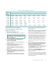
Table 8-1. Sample DIMM Configurations
Total
Desired
Memory
DIMM Sockets
DIMM A DIMM B DIMM C DIMM D DIMM E DIMM F DIMM G DIMM H
64 MB 32 MB 32 MB None None None None None None
128 MB 32 MB 32 MB 32 MB 32 MB None None None None
128 MB 128 MB None None None None None None None
192 MB 128 MB 32 MB 32 MB None None None None None
320 MB 128 MB 128 MB 32 MB 32 MB None None None None
512 MB 128 MB 128 MB 128 MB 128 MB
1024 MB 128 MB 128 MB 128 MB 128 MB 128 MB 128 MB 128 MB 128 MB
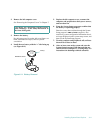
CAUTION: See “Protecting Against Electro-
static Discharge” in the safety instructions at
the front of this guide.