


112 Display
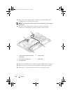
4
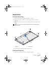
Align the display assembly over the chassis and gently snap the chassis into
place.
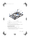
5
Replace the five screws that secure the chassis to the display assembly.
6
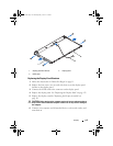
Replace the 13 screws that secure the chassis to the display bezel.
7
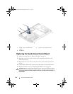
Route the camera cables, touch-screen control board cables, backlight
cable and LVDS cable through the routing guides.
8
Connect the cables to the connectors on the system board, touch-screen
control board, AV board, and the converter board.
9
Replace the middle frame. See "Replacing the Middle Frame" on page 72.
10
Replace the processor heat-sink fan. See "Replacing the Processor
Heat-Sink Fan" on page 76.
11
Replace the AV board. See "Replacing the Audio Video (AV) Board" on
page 45.
12
Replace the system-board shield. See "Replacing the System-Board Shield"
on page 54.
13
Replace the rear I/O cover. See "Replacing the Rear I/O Cover" on page 40.
14
Replace the side I/O cover. See "Replacing the Side I/O Cover" on page 41.
15
Follow the instructions from step 4 to step 6 in "Replacing the Optical
Drive" on page 29.
16
Replace the VESA mount. See "Replacing the VESA Mount" on page 38.
17
Replace the rear-stand assembly. See "Replacing the Rear-Stand Assembly"
on page 36.
18
Replace the back cover. See "Replacing the Back Cover" on page 21.
CAUTION: Before turning on the computer, replace all screws and ensure that no
stray screws remain inside the computer. Failure to do so may result in damage to
the computer.
19
Connect your computer and all attached devices to electrical outlets, and
turn them on.
book.book Page 112 Thursday, May 3, 2012 1:21 PM