


Wireless Mini-Card 63
Replacing the Mini-Card(s)
CAUTION: The connectors are keyed to ensure correct insertion. Use of
excessive force may damage the connectors.
CAUTION: To avoid damage to the Mini-Card, ensure that there are no cables or
antenna cables under the Mini-Card.
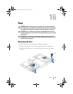
1
Follow the instructions in "Before You Begin" on page 11.
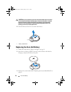
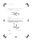
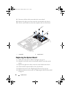
2
Align the notch on each Mini-Card with the tab in the system-board
connector.
3
Insert the Mini-Card at a 45-degree angle into the system-board connector.
4
Press the other end of the Mini-Card down and replace the two screws that
secure the Mini-Card to the system-board connector.
5
Connect the appropriate antenna cable(s) to the Mini-Card you are
installing. The following table provides the antenna cable color scheme for
the Mini-Card(s) supported by your computer.
6
Replace the system-board shield. "Replacing the System-Board Shield" on
page 54.
7
Replace the rear I/O cover. See "Replacing the Rear I/O Cover" on page 40.
8
Replace the side I/O cover. See "Replacing the Side I/O Cover" on page 41.
9
Replace the rear-stand assembly. See "Replacing the Rear-Stand Assembly"
on page 36.
10
Replace the back cover. See "Replacing the Back Cover" on page 21.
CAUTION: Before turning on the computer, replace all screws and ensure that no
stray screws remain inside the computer. Failure to do so may result in damage to
the computer.
Connectors on the Mini-Card Antenna Cable Color Scheme
WLAN (2 antenna cables)
Main WLAN (white triangle)
Auxiliary WLAN (black triangle)
white
black
TV tuner (1 antenna cable)
black
book.book Page 63 Thursday, May 3, 2012 1:21 PM