


EPSON Stylus PHOTO 810/820/830 Revision B
Disassembly and Assembly Disassembly 100
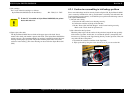
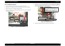
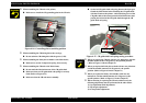
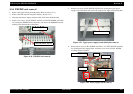
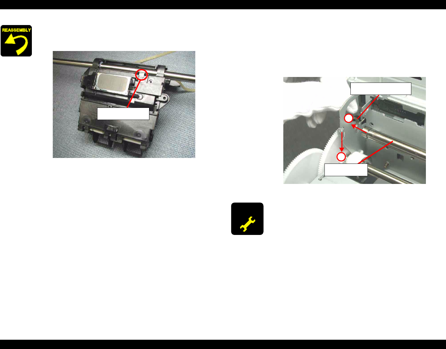
When assembling the CR unit to the printer,
Make sure to install the CR grounding plate in the CR unit.
Figure 4-16. Grounding plate assembling position
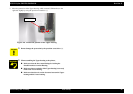
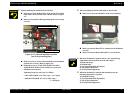
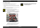
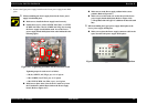
When assembling the CR timing belt to the carriage,
Do not stain the CR timing belt with the grease (G-58).
When assembling the Pulley driven holder to the Main frame,
Make sure to set the Compression spring 19.6 correctly.
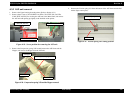
When assembling the CR unit to the Main frame,
Do not touch the lubrication area of the CR guide shaft.
Make sure that two CR guide shaft rod springs is correctly
fixed. (Refer to Figure 4-13)
Make sure that the CR unit moves smoothly.
CR grounding plate
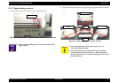
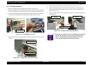
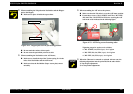
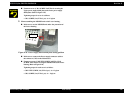
Set the left CR guide shaft rod spring between the Spur gear
60 and the Main frame before installing the CR guide shaft
with the CR unit to the printer. And, install the groove of the
CR guide shaft to the cutout portion of the Main frame after
passing the left end of the CR guide shaft through the CR
guide shaft rod spring.
Figure 4-17. CR guide shaft rod spring setting procedure
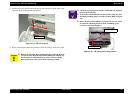
ADJUSTMENT
REQUIRED
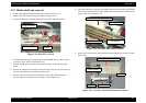
When you replace the CR unit with new one, lubricate it with the
suitable amount of the G-58 grease by the specified position.
( Refer to Figure 6-4 in the Chapter 6.)
When you replace the Pulley driven shaft with new one, lubricate
it with the suitable amount of G-58 grease by the specific
position. (Refer to Figure 6-9 in the Chapter 6.)
When you replace the Pulley driven holder with new one,
lubricate it with the suitable amount of G-58 grease by the
specific position. (Refer to Figure 6-5 in the Chapter 6.)
When removing or replacing the CR unit with new one, the
following adjustment must be performed in the order below.
1) Gap adjustment (Bi-d adjustment)
2) Top margin adjustment
3) 1st dot position adjustment
CR guide shaft rod spring
CR guide shaft
1
2