


EPSON Stylus PHOTO 810/820/830 Revision B
PRODUCT DESCRIPTION INTERFACE 22
1.3.3 USB Interface
Standard : Based on
“Universal Serial Bus Specifications Rev. 1.1”
“Universal Serial Bus Device Class Definition
for Printing Devices Version 1.1”
Bit Rate : 12Mbps (Full Speed Device)
Data Encoding : NRZI
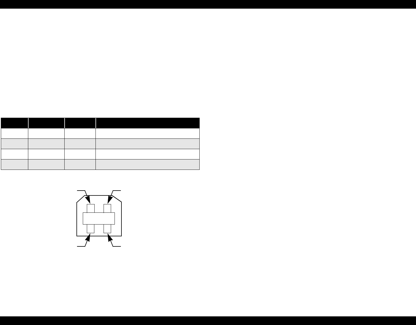
Adaptable Connector : USB Series B
Recommended Cable Length : 2 meters
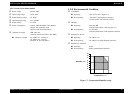
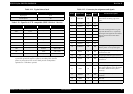
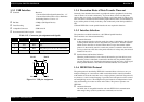
Figure 1-9. USB pin Assignment
1.3.4 Prevention Hosts of Data Transfer Time-out
Generally, hosts abandon data transfer to peripherals when a peripheral is in the busy
state for dozens of seconds continuously. To prevent hosts of time-out, the printer
receives data very slowly, several bytes per minute, even if the printer is in busy state.
This slowdown is started when the remaining input buffer becomes several hundreds of
bytes, and the printer is finally in the busy state continuously when the input buffer is
full.
USB and IEEE1284.4 on the parallel interface do not require this function.
1.3.5 Interface Selection
The printer has two built-in interfaces : the USB and parallel interface.
These interfaces are selected automatically.
Automatic Selection
In this automatic interface selection mode, the printer is initialized to the idle state
scanning which interface receives data when it is powered on. Then the interface
which receives data first is selected. When the host stops data transfer and the
printer is in the stand-by state for seconds, the printer is returned to the idle state.
As long as the host sends data or the printer interface is in busy state, the selected
interface is let as it is.
Interface State and Interface Selection
When the parallel interface is not selected, the interface gets into the busy state.
When the printer is initialized or returned to the idle state, the parallel interface
gets into the ready state. Caution that the interrupt signal such as the -INIT signal
on the parallel interface is not effective while that interface is not selected.
1.3.6 IEEE1284.4 Protocol
The packet protocol described by IEEE1284.4 standard allows a device to carry on
multiple exchanges or conversations which contain data and/or control information
with another device at the same time across a single point-to-point link. The protocol is
not, however, a device control language. It provides basic transport-level flow control
and multiplexing services. The multiplexed logical channels are independent of each
other and blocking of one has no effect on the others. The protocol operates over
IEEE1284.
Automatic Selection
An initial state is compatible interface and starts IEEE1284.4 communication
when magic strings (1284.4 synchronous commands) are received.
Table 1-15. Connector pin assignment and signals
Pin No. Signal name I/O Function description
1 VCC - Cable power. Max. power consumption is 2mA.
2 -Data Bi-D Data
3 +Data Bi-D Data, pull up to +3.3V via 1.5K ohm resistor.
4 Ground - Cable ground
Pin #1
Pin #3
Pin #2
Pin #4