


EPSON Stylus PHOTO 810/820/830 Revision B
Appendix Connector Summary 136
7.1 Connector Summary
7.1.1 Major Component Unit
The major component units of this printer are as follows.
C418 Main/Main-B Board
Power Supply Board (C417PSB/PSE)
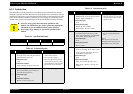
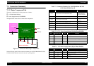
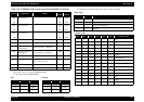
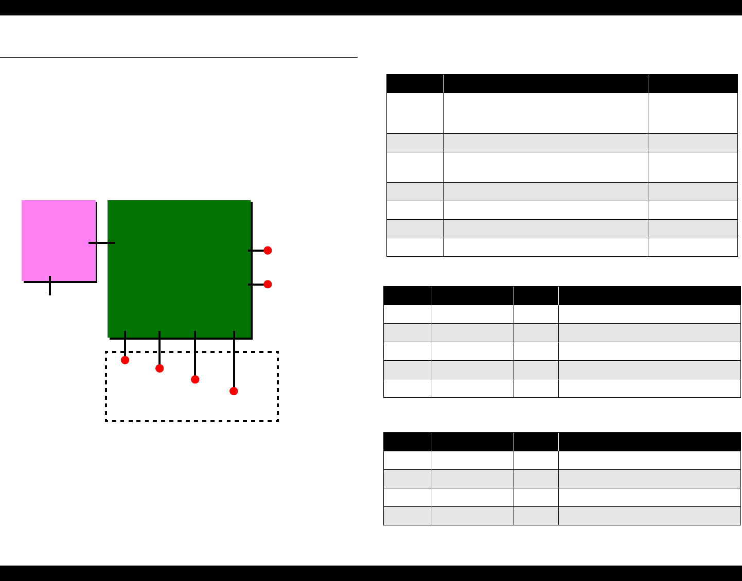
The figure below shows how to connect these components.
Figure 7-1. Connection of the major components
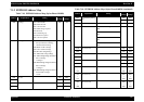
See the following tables for the connector summary for the C418 Main/Main-B, C429,
C483/C484 Main-B board and each connector’s pin alignment.
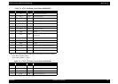
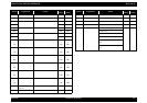
Table 7-3. CN2-Power supply board (Stylus Photo 820/830)
CN8, CN9 CN12 CN4
Parallel I/F
CR motor
Printhead
PF motor
C418 MAIN/Main-B
C429 Main
C483/484 Main-B
CN7
CN1
CN2
HP/PE sensor
C417PSB/PSE
C482 PSH
CN2
AC power
Printer mechanism
USB I/F
CN3
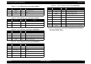
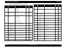
Table 7-1. Connector Summary for C418 Main/Main-B/C429/
C483 Main-B/C484 Main-B
Connector Function Table to refer to
CN1 For connection with the Parallel interface
Refer to 1.3.1
"Parallel Interface
(Forward Channel)"
CN2 For connection with the Power supply board Table 7-2
CN3 For connection with the USB
Refer to 1.3.3 "USB
Interface"
CN4 For connection with the HP/PE sensor Table 7-4
CN7 For connection with the PF motor Table 7-6
CN8, CN9 For connection with the printhead Table 7-7, Table 7-8
CN12 For connection with the CR motor Table 7-9
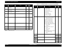
Table 7-2. CN2 - Power Supply Board (Stylus Photo 810/820)
Pin Signal Name I/O Function
1 PSC --- PSC signal
2 GND --- Ground
3 +42V --- Mechanism drive power supply
4 GND --- Ground
5 +5V --- Logic power supply
Pin Signal name I/O Function
1 +42V --- Mechanism drive power supply
2 +5V --- Logic power supply
3 GND --- Ground
4 PSC --- PSC signal